Specialize in ball bearings, roller bearings, thrust bearings, thin section bearings etc.
Follow me on:
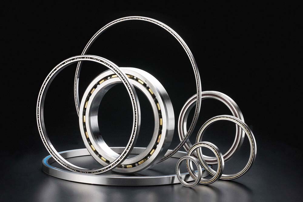
Everything You Should Know About Thin Section Bearings
Thin-section bearings are designed for space-constrained applications and help meet challenging specifications often found in high-tech applications. The construction of thin-section bearings helps save space, reduce weight, improve running accuracy and design flexibility. These thin section bearings are designed in a limited number of widths and thicknesses/cross sections. Each cross-section has a wide range of pore sizes. As the pore size increases, the cross-section remains constant. Thin-section bearings feature ultra-precision raceways that provide a smooth surface finish that helps reduce friction. The bearings also feature high-quality ball assemblies to ensure smooth rolling performance. Thin section bearings are used in industries such as medical equipment, robotics, construction equipment, food processing and textile machinery.
Saves weight
Saves space
Reduces friction
High speed performance
High rotation accuracy
Accurate positioning
Variety of cross sections and sizes
Different types of thin section bearings
Several different types of thin section bearings are available depending on the application needs. ABMA STD 26.2 – Thin Section Ball Bearings Inch Designs – This standard specifies tolerances for dimensions, running accuracy and internal clearance. Thin section bearings vary in size and width depending on their use and application. These bearings are constructed of 52100 chrome steel and 440C stainless steel. They also come in a series including SR Series, 6700 Series, 6800 Series, 63800 Series and 6900 Series. Certain sizes of these bearings can be produced as open, shielded or sealed. Bearings are considered thin section bearings when the bore diameter is greater than 4 times the radial cross section. There are three contact types for thin section bearings: radial contact type C, angular contact type A and four-point contact type X.
Radial contact C-type thin-walled bearings are mainly used to bear radial loads.
Angular contact type A thin-section bearings are designed to withstand higher thrust and axial loads.
Four-point contact X-type thin-section bearing has a special raceway, which forms four contact points with the ball bearing, so the bearing can bear radial and thrust loads.
Thin section bearings also come in many other variants. Thin section bearings can also be coated with specialized coatings such as thin dense chrome plating or various other coatings.
BearingType
Contact
Radial
Axial
Moment
ReversingAxial
CombinedRadial-Thrust
C
Radial
Excellent
Good
Good
Good
Good
A
Angular
Good
Excellent
Do Not Use
Do Not Use
Good
X
4-Point
Poor
Good
Excellent
Excellent
Poor
Angular Contact Type A Thin Section Ball Bearings
In applications with high axial loads, type A angular contact ball bearings should be used. This bearing also works well in radial or combined radial thrust applications. Type A bearings should never be used alone for moment loads or reverse axial loads. Two A-type bearings are usually used as a duplex pair.
Radial Contact Type C Thin Section Ball Bearings
Type C radial contact ball bearings are designed with deep ball grooves to withstand high loads. Although this bearing is primarily used for radial load applications, it can also accommodate moderate axial loads, reverse axial loads and moment loads.
4-Point Contact X-Type Thin Section Ball Bearings
Type X or 4 point contact ball bearings are ideal for moment loads. Type X bearings are designed with gothic arched raceways that create 4 points of contact between the balls and the raceway. This design is well suited for moment loads and opposing axial loads. X-type bearings can be used for other lightly loaded conditions, but are not recommended to replace C-type or A-type bearings under purely radial loads.
Choose the right thin section bearing
After considering the maximum static and dynamic load, the required bearing life, referring to the catalog data – size, speed and load rating, operating environment, rotational performance, mounting conditions and temperature, the final type, size and bearing arrangement can be selected to determine the bearing Specification. Accuracy class, clearance, lubricant and type of closure (shield or seal) also form an important part of specifying the right bearing.
When the load is mainly in the radial direction, the use of radial thin-walled bearings can also support limited axial and reverse loads. For this type, usually the best choice is a standard series bearing.
Angular contact type thin section bearings are used when high thrust and axial loads are present. These types of bearings, when used as a duplex pair (matched set), offer increased load capacity and rigidity, as well as high rotational accuracy.
4-point contact bearings have a unique raceway design that allows one bearing to handle radial, thrust and overturning moment loads. Viewed in cross-section, the raceway has a Gothic arch rather than a true radius. This arch creates 4 points of contact with the balls and the raceway. Designers can choose a 4-point contact bearing arrangement.
If corrosion is a concern, thin section bearings in 52100 chrome steel and martensitic stainless steel are usually available. Different sealing options are available to prevent contamination. Different ball separators are available for non-standard operating conditions. All of these things must be considered when specifying.
Capacity and Fatigue Life of Ball Bearings
The BASIC DYNAMIC RADIAL LOAD RATING, C, or “dynamic capacity”, for a ball bearing is that calculated, constant radial load at which 90% of a group of apparently identical bearings with stationary outer rings can statistically endure 106 revolutions of the inner ring. ANSI/ABMA Standard 9 with correction factors for race curvatures was used to calculate the catalog ratings.
The DYNAMIC THRUST and DYNAMIC MOMENT LOAD RATINGS are also shown in the product tables. The ratings shown are a guide for the maximum loads under which these bearings should be operated with either pure thrust or pure moment loading. Thrust ratings are 2.5 to 3.0 times the radial ratings depending on the bearing type and cross section. These load ratings are not additive. For combined radial and thrust loads, an equivalent radial load is to be calculated.
The BASIC STATIC LOAD RATING, Co, or “static capacity”, is that uniformly distributed load, which produces a maximum theoretical contact stress of 609,000 psi. At this contact stress permanent deformation of ball and raceway occurs. This deformation is approximately .0001% of the ball diameter.
The RATING LIFE, L10, is a statistical measure of the life which 90% of a large group of apparently identical ball bearings will achieve or exceed. For a single bearing, L10 also refers to the life associated with 90% reliability. Median Life, L50, is the life which 50% of the group of ball bearings will achieve or exceed. Median life is approximately five times the rating life.
The relationship between rating life, load rating, and load is:
L10 = (C/P)3 with L10 = rating life (106 rev) C = basic dynamic radial load rating (lbf) P = equivalent radial load (lbf)
To obtain the rating life in hours, use:
L10 hrs = 16667/n * (C/P)3 with n = speed (rpm)
The Equivalent Radial Load is defined as:
P = XFr + YFa with Fr = radial load (lbf) Fa = axial load (lbf) X = see below Y = see below
Adjustment Factors for Rating Life
If a bearing design and operation deviates significantly from normal, it may be necessary to use additional factors to estimate the fatigue life Ln.
Reliability is the percentage of a group of apparently identical ball bearings that is expected to attain or exceed a specified life. For an individual bearing it is the probability that the bearing will attain or exceed a specified life. Typical bearing lives are calculated for 90% reliability. The life adjustment factors for other reliability numbers are shown below.
Reliability %
Ln
Reliability Factor a1
90
L10
1.00
95
L5
.62
96
L4
.53
97
L3
.44
98
L2
.33
99
L1
.21
Material Factor a2
For standard bearings the material factor a2 is equal to 1.00. Factor a2 is determined by material processing, forming methods, heat treatment, and other manufacturing methods. Some commonly used material factors are listed below:
Material, Condition
a2 max
52100, Air melt
1.00
52100, Vacuum degassed
1.50
52100, Air melt & TDC Plate
2.00
52100, Vacuum melt, (CEVM)
3.00
440C, Air melt
1.00
440C, Vacuum melt (CEVM)
2.00
M50, Vacuum melt (CEVM)
5.00
M50, Vacuum re-melt (VIM-VAR)
8.00
Application Factor a3
The application factor a3 is equal to 1.0 for most applications. Unusual or extreme conditions in certain applications such as low speed, shock loading, vibration, and extreme temperature may lower the application factor to 0.50. Contact your RBC Sales Engineer for help in determining this factor for your special application.
Load and Speed Limits
For combined simultaneous loading, equivalent radial or thrust loads must be considered. Typically, Type C bearings are designed for radial load applications; moderate thrust and/or moment loads can be combined with radial loads. For thrust load applications, type A bearings are used; any radial loads can only be combined with thrust loads. X-type bearings are mainly used for reverse thrust and moment loads, and pure radial loads should not be applied.
The limiting speeds shown in the product tables are based on lubrication standards. Calculate the unsealed bearing speed assuming the bearing is lubricated to MIL-L-3150. Calculate the limiting speed for a sealed bearing assuming the bearing is lubricated with MIL-G-23827 grease. If the bearings are lubricated with alternative oils or greases, new limiting speeds must be calculated, see operating conditions.
Operating conditions
Lubricants serve many very important purposes in ball bearings, including:
Protect bearing surfaces from corrosion
Reduces rolling and sliding friction
Prevents metal-to-metal contact between balls and raceways
Provides a barrier against external contaminants (grease)
Remove heat (oil)
Standard AUB thin section ball bearings are oil or grease lubricated. Unsealed bearings K series are fully coated with MIL-L-3150 oil and drain excess oil. Sealed bearings are lubricated with MIL-G-23827 grease. The outer surface of sealed bearings is coated with a thin layer of the same grease to prevent corrosion. Additional lubricant is also provided. Your AUB Sales Engineer can assist you in selecting the proper lubricant for your particular application.
Temperature
Standard AUB thin section ball bearings can operate in temperatures ranging from -65°F to 250°F. If the bearing is temperature stabilized, it can reach temperatures as high as 350°F. Through the use of specialty materials, AUB can provide bearings that can operate down to 700°F. For advice on bearings operating above 250°F, please contact your AUB Sales Engineer.
Speed limit
The limiting speed of a bearing depends on many different factors including bearing size, bearing type, ball separator design, lubrication and load. The limiting speed of bearings shown in this catalog is determined using the following formula:
Bearing Type
Load Condition
k Value
Grease
Oil
C or A
Radial or Thrust
16
20
X
Thrust
10
12
X
Radial, Combined Radial & Thrust, or Moment
3
4
The k values shown give the maximum speed at which a typical thin section ball bearing can operate. It is recommended to reduce the operating speed of large diameter bearings in a given series to 40% of the calculated rating to avoid excessive bearing temperatures. Rated speed is also affected by loading conditions, lubrication, alignment and ambient temperature. All of these factors must be considered when designing a thin section ball bearing for your application.
Duplex Pairs and Axial Preload
Duplex pair
Duplex bearings are a pair of angular contact AUB thin section ball bearings, specially ground and available as a pair. Duplex pairs can be used to provide accurate shaft positioning for increased capacity or increased stiffness of bearing assemblies. A pair of AUB thin section ball bearings are ground so that when mounted with the recommended fit there will be no internal play in the bearings. There are three basic mounting methods to suit different load requirements:
Back-to-Back, DB B-Type
Back-to-Back (DB) Type B
Face-to-Face (DF) Type F
Tandem (DT), Type T
Heavy radial load
Combined thrust and radial loads
Reverse thrust load
Excellent rigidity
Moment load
Accuracy class
AUB thin section ball bearings are available in four accuracy classes. AUB Precision grades 0, 3, 4 and 6 correspond to ABMA ABEC grades 1F, 3F, 5F and 7F respectively. Tolerances for bearing bore, outside diameter, radial runout, axial runout and radial clearance are shown in the tolerance table.
Shaft and housing fit
Proper shaft and housing fit is critical to the successful operation of thin section ball bearings. The internal clearance of the bearing will be reduced proportionally by the interference fit. In addition, the roundness of the shaft and housing will directly affect the roundness of the raceways of the inner and outer rings. For most applications, the inner race is rotating while the load is stationary relative to the outer race. In this case, a light press fit to the shaft is recommended. Recommended shaft and housing fits are shown in the tolerance tables.
Mounting Arrangements
When selecting a mounting arrangement for AUB thin section ball bearings, the loading conditions must first be considered. A pair of duplex angular contact bearings can be used for combined loads, moment loads or heavy thrust loads. Combinations of A and C, A and X, or C and X bearings are common mounting arrangements. Two X-type bearings should never be mounted on the same shaft. There may be many different bearing arrangements carrying the same load, some typical mounting arrangements are shown below.
Heavy radial load
Type C bearings are primarily designed for heavy radial loads. Two bearings can be mounted on the same shaft as shown. By axially securing one bearing and allowing the other to float, this configuration allows for differential expansion between the housing and shaft (caused, for example, by temperature differences) without adding axial stress to the bearing. Although Type C bearings are designed for radial loads, they can accommodate moderate thrust, moment and reverse loads.
Reverse load
Type C bearings are primarily designed for heavy radial loads. Two bearings can be mounted on the same shaft as shown. By axially securing one bearing and allowing the other to float, this configuration allows for differential expansion between the housing and shaft (caused, for example, by temperature differences) without adding axial stress to the bearing. Although Type C bearings are designed for radial loads, they can accommodate moderate thrust, moment and reverse loads.
Heavy combined load
For heavy combined loads, other special mounting arrangements are available. A pair of double A type bearings can be used with a floating type C bearing as shown above. In this configuration, Type A bearings will carry thrust loads and some radial loads, while Type C bearings will only carry radial loads. X-type bearings can be substituted for duplex A-type bearings for lower thrust loads, as shown in the second diagram.
Heavy combined or moment loads
Alternative installations for heavy combined loads or moment loads are shown below. A pair of duplex Type B bearings can accommodate high thrust, radial and moment loads. Type X bearings can replace duplex bearings in lighter-load applications to save weight, space and cost.
Custom Function
AUB offers many different lubricants for special applications. Greases are available specially designed for high speed, low torque, water resistant, high temperature resistant, vibrating motion and food machinery. Other lubricants, such as dry film, are suitable for vacuum and space applications.
Challenge us: There are many design options available for solving difficult application problems.
Material
Standard bearings shown in the catalog have SAE 52100 steel rings and balls. AUB Thin Section Ball Bearings can be fabricated from other specialty bearing steels to provide corrosion resistance, high temperature resistance, alternative load capacity or chemical compatibility.
Ring. AUB manufactures thin section ball bearings from SAE 440C stainless steel to provide corrosion resistance. As an alternative to stainless steel rings, the entire surface of the ring can be plated with spherical thin dense chrome (TDC). This AMS 2438 compliant plating achieves a molecular bond that will not flake, flake, or separate from the substrate. TDC boards have a hardness of HRC 70 – 78 and can withstand temperatures well beyond the range of the substrate.
Special AUB Thin Section Ball Bearings are manufactured from Aluminum, 300 Series Stainless Steel, 17-4 Stainless Steel and other metals.
Ball. Some of the specialty ball materials available include 440C Stainless Steel, 300 Series Stainless Steel, Silicon Nitride, and M-50 Steel.
lubricating
AUB offers many different lubricants for special applications. Greases are available specially designed for high speed, low torque, water resistant, high temperature resistant, vibrating motion and food machinery. Other lubricants, such as dry film, are suitable for vacuum and space applications.
Seal
Standard seals for thin section ball bearings are molded from elastomer (Buna N). Polytetrafluoroethylene (PTFE) seals, glass fiber reinforced PTFE seals, stainless steel boots and many other options are available for low torque and other special applications.
Radial play
If a non-recommended mounting fit is used, the radial clearance (radial clearance) of thin-section ball bearings needs to be determined in advance. Special radial clearances may be required for temperature differences across the bearing, for housing and shaft materials with different coefficients of thermal expansion, or for changes in the bearing’s operating characteristics. Radially preloaded bearings are measured to meet bore and outside diameter tolerances before preloading.
Preload of duplex bearings
Standard duplex bearings are ground so that under nominal conditions a slight axial preload occurs on the bearing. In some applications, it may be necessary to increase bearing stiffness. In these cases, double-sided grinding is possible, resulting in greater axial loads in the mounted bearing. This load can be increased or decreased to meet specific application requirements. Please consult your AUB sales engineer for special requirements.
Mounting features such as flanges, anti-rotation tabs and mounting holes can be incorporated on the inner and outer rings. Mating components such as gears and housings can be integrated into the bearing rings to improve performance and cost.
Splitter
Standard AUB thin section ball bearings, series KA to KG and JU, are manufactured with brass separators. The KAA series includes nylon separators. Type A bearings contain integral round bag separators, while C and X bearings have snap-on separators. The four basic separator materials are brass, nylon, phenolic, and stainless steel. The diagram below schematically illustrates the effect of cage design and material on bearing performance. Specific material advantages and limitations are listed on page 39. In contrast, a one-piece round pocket design can be about twice as fast as a snap-on design. Exact speed limits depend on bearing size, bearing type, lubrication and load. For assistance in selecting the appropriate separator for a particular application, please contact your AUB Sales Engineer.
Typical Application
Thin section ball bearings are often used in applications with space, weight and load constraints. Some typical applications for standard AUB thin section ball bearings include: