
Bearing Manufacturer & Supplier
Specialize in ball bearings, roller bearings, thrust bearings, thin section bearings etc.
Follow me on:


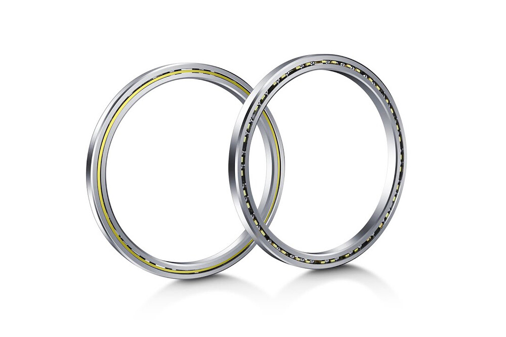
The Ultimate Guide to Thin Section Bearings
Thin section bearings were developed when standard deep groove ball bearings were insufficient for certain applications. Thin-section bearings have a very small cross-section relative to their diameter. This design determines that the thin-section bearing has a smaller design volume and lower mass, while achieving high rigidity and operating accuracy.


Rolling bearing series standardized according to DIN ISO, the cross-section of thin-section bearings increases with increasing diameter, and all sizes of thin-section bearings in a series have the same cross-section. “There are several definitions of thin-section bearings in the industry, one of the most common is that a bearing is considered thin-section when the diameter is than 4 times greater than the radial cross-section. Cross-section dimensions can vary, but are typically ball Twice the diameter.” Typical applications for thin-section bearings are those critical applications where space is limited, weight must be minimized, absolute accuracy must be maintained and load and torque requirements still require the use of ball bearings. In such applications, thin section bearings help reduce costs compared to standard deep groove ball bearing sizes and have the advantage of using only one bearing with little impact on overall weight.
Classification of thin section bearings
Each thin-section bearing application has specific requirements. These potential differences make some thin-section bearings better options than others. When it comes to thin section bearings, there are three different types to consider:

A type thin section bearing

C type thin section bearing

X type thin section bearing
Type A – Angular Contact Thin Section Bearings
Angular contact thin-section bearings are mainly used in harsh environments with high axial loads. It is generally not recommended to use a single A-type angular contact thin section bearing to support moment or reverse axial loads, but two A-type bearings as a duplex bearing pair can easily support such loads. The stability, load capacity and repeatability of A-type angular contact thin-section double bearing pairs are better than those of C-Type thin-section bearings.
Both rings of Type A angular contact thin-section bearings have extra-deep ball grooves (groove depth = 25% of ball diameter).
A-type angular contact thin-section bearings have sufficient radial clearance to produce a 30° contact angle (α) that can withstand axial loads.
The cage of the A-type angular contact thin-section bearing is in a circular bag, in which the number of balls accounts for about 67% of all balls.
TYPE A Thin Section Bearing LOAD CONDITION | ||||
Radial | Axial | Moment | Reversing | Combined |
Good | Excellent | Use in Pairs | Use in Pairs | Good |
Provides greater (one-way) axial load capacity than C- or X-type bearings:
The outer ring is usually counterbored to reduce one shoulder of the raceway, and the outer ring is mounted over the inner ring, balls and cage for convenience (with the help of the temperature difference between the two rings).
A-type angular contact thin-section bearing is a non-separable bearing that can bear larger radial loads and simultaneously bear a large amount of axial load in one direction.
When carrying axial loads, the surfaces of the inner and outer rings of Type A angular contact thin-section bearings are approximately flush, minimizing preload adjustments.
A-type angular contact thin-section bearings are usually installed opposite another bearing of the same type so that axial loads exist to establish and maintain the contact angle and accommodate reverse axial loads with minimal axial movement
Type C – Radial Ball Thin Section Bearings
C-type radial contact ball thin-section bearings adopt a deep groove ball design whose grooves can withstand high loads and are the preferred solution for applications with radial loads. As you would expect, Type C thin section bearings can also handle moderate axial loads, reverse axial loads and moment loads.
Both rings of C-type radial contact ball thin-section bearings have extra-deep ball grooves (groove depth = 25% of ball diameter).
The inner ring has an eccentric displacement within the outer ring, about half the distance of the ball.
The rings are positioned concentrically and the cage/separator separates the balls evenly around the entire circumference.
Type C radial contact ball thin section bearings perform best when there is a small amount of play (radial clearance, which can be increased or decreased to meet operating conditions) between the ball and the ring.
TYPE C Thin Section Bearing LOAD CONDITION | ||||
Radial | Axial | Moment | Reversing | Combined |
Excellent | Good | Good | Good | Good |
Type C radial contact ball thin section bearings are designed so that the ball and ring contact in the center plane of the ball when only radial loads are applied. Although primarily designed for radial load applications, C-type bearings have no filled grooves and can handle some axial loads in either direction. The ability to withstand axial loads depends on the amount of clearance in the bearing after installation. By increasing the radial clearance above the standard value, C-type bearings can have a larger contact angle under axial load, resulting in greater axial load capacity. In this case, it is recommended to adjust the bearing against another bearing of similar construction to reduce axial movement under reverse axial loads. Used in this manner, the bearings are essentially angular contact ball bearings rather than radial contact ball bearings.
X type - four-point contact thin section bearing
Unlike Type A and Type C thin section bearing designs, Type X four-point contact thin section bearings are made with Gothic archways that create four points of contact between the balls and raceways in the bearing. This design makes four-point contact thin section bearings a prime option for applications requiring sufficient torque or reverse axial loads in a small package. However, Type X four-point contact thin section bearings do have a lower ability to carry a wide range of radial loads than Type X thin section bearings. Type X four-point contact thin section bearings are not recommended as a replacement for type C or type A thin section bearings in environments intended for pure radial loads. It should be noted that the speed (rpm) of X-type four-point contact thin section bearings is a particular concern when combined with radial loads when applied with axial or moment loads.
TYPE X LOAD CONDITION | ||||
Radial | Axial | Moment | Reversing | Combined |
Poor | Good | Excellent | Excellent | Poor |
Type X bearings differ from Type A and Type C bearings in the geometry of their raceway grooves:
Type C: The centers of the radii are located in the center plane of the ball.
Type A: The ferrule and the ball are in angular contact, and the groove radius center is offset by an equal amount on both sides of the ball center plane.
X-type: The grooves in each ring have two radii with their centers offset from the center plane of the ball.
The groove depth in Type X bearings is the same as Type A and Type C (25% of the ball diameter).
The specific features of the “Gothic Arch” are:
Enables a single X-type bearing to bear three types of loads (radial, axial and moment) simultaneously (while standard size bearings are usually designed to bear only radial and axial loads).
Making it an ideal bearing for many applications, as a single four-point contact ball bearing can often replace two bearings, such as a set of two A-frame bearings arranged back-to-back, thus providing a simplified design.
The axial load applied to the inner ring from right to left is transferred from the inner ring to the ball at point B.
The load is then transferred through the ball to point D where it is transferred to the outer ring and supporting structure.
Line of action BD forms a nominal 30° contact angle (α) with the radial centerline of the bearing.
Due to the elastic deformation of the ball and raceway along the load transfer line, the load on the ball is released at points A and C, allowing smooth rotation around the axis perpendicular to the BD line.
When an axial load is applied to the inner ring from left to right, a similar load transfer occurs between point C and point A.
Like C-type bearings, X-type bearings usually have radial clearance. However, the nominal contact angle and axial load capacity of type X bearings do not depend on the clearance. When the axial or moment load is considerable, the gap should be minimized to prevent the contact angle from being too large. The main thing to note is that it is recommended that the X-bearing be used alone. It is not recommended to use two X-bearings on a common shaft as this may lead to unacceptable frictional moments.
Loads on thin section bearings
Bearings support shafts or housings, allowing them to run freely under load. Above we analyzed a variety of thin-section bearings that can withstand radial, axial and moment loads. Loads can be applied to thin-section bearings in one of two cardinal directions, where the resultant moment load (M) can be calculated as:
M = Fa Sa + Fr Sr
M | = | moment load [N·m] |
Fa | = | axial load [kN] |
Sa | = | offset distance from the bearing axis [m] |
Fr | = | radial load [kN] |
Sr | = | offset distance from the radial plane [m] |
Axial loads (Fa) are parallel to the shaft (the axis of rotation of the bearing), while radial loads (F r ) are at right angles to the axis of rotation. When these loads deviate from the bearing axis (distance Sa) or the radial plane (distance Sr< /span>), a final moment load (M) is created. The use of computer software has made the method of determining bearing life complex and accurate than previous manual calculations. The actual load is applied to the bearing and the resultant load on each ball in that bearing is determined. From this calculation, the static safety factor and the basic rating life L10 can be determined.
Main radial load
The larger the bearing clearance, the fewer balls there are to carry the load, resulting in a shorter dynamic life.
A large bearing preload may overload the bearing before load is applied.
Main axial loads and moment loads
A larger gap will allow a larger contact angle than the ball to raceway and therefore better adapt to the applied load.
However, the elliptical area of ball contact with the raceway may be truncated above the edge of the raceway, causing other problems.
Greater preload may overload the bearing again before load is applied.
Calculating the static safety factor or dynamic life requires the help of computer software to determine the individual ball loads throughout the bearing – using Reali-Design (for Reali-Slim inch bearings) or Reali-Design MM (for Reali-Slim metric bearings) software. Once these are calculated, the maximum load sphere is used to determine the maximum stress level and thus the static safety factor. All ball loads are used in a weighted analysis to determine the basic rating life, L10.
Limiting speed of thin section bearings
Generally speaking, determining the maximum safe operating speed depends largely on past experience. The factors that limit the rotation speed of bearings are very complex, including:
Bearing diameter
Bearing diameter to cross-section ratio
Bearing type and internal configuration
Ratio of raceway groove radius to ball diameter
Bearing internal radial clearance or preload
Working contact angle
Bearing accuracy (runout)
Ball cage/separator materials and design
Installation accuracy (roundness, flatness under load)
Lubrication
Ambient temperature and heat dissipation measures
Seals
Load

While it is not possible to set precise speed limits, practical applications and the experience of the AUB test laboratory provide a basis for setting general limits. Assume the bearings are installed correctly and have adequate heat dissipation. These limits are based on a full service life of 1 000 000 revolutions. Higher speeds can be tolerated if shorter lifetimes are acceptable. For speeds approaching or exceeding the limit calculated using the limit speed (n) formula, special attention must be paid to lubrication and heat:
Grease should be specially designed for high speed bearings.
The frequency of relubrication must be sufficient so that sufficient lubricant is always available.
If oil is used, viscous drag should be minimized by controlling the level, using an oil slinger, and/or metering small amounts of liquid or mist.
The effects of air turbulence at high speeds can make it very difficult to introduce oil to critical surfaces, so the design of the lubrication system becomes very important.
The following calculations can be used for open type Reali-Slim inch series thin section ball bearings at continuous speeds.
n = 1 000 fl Cf/d
| Cf | = | calculation factor (table 1) |
| d | = | bore diameter [mm (in)] (product table) |
| fl | = | reduction factor (table 2) |
| n | = | limiting speed [r/min] |


How to choose the best thin section bearing for your application?
The type and magnitude of loads required in a particular application determines which thin-section bearing is most appropriate. For example, in environments where there are axial loads in one direction, AUB recommends the use of its dedicated Type A angular contact ball bearings. This option is also ideal for radial or combined thrust applications. Still, it is not suitable for applications that need to support moment loads or reverse axial loads.
Once larger moment loads have been determined, AUB will recommend the use of X-pattern or 4-point contact ball bearing options. The design utilizes a “gothic arch” raceway to create four points of contact between the ball and raceway. Making it the perfect solution for reverse axial loads and ideal for moment loads. Although type X bearings may be used in other light load conditions, replacement of type C or A bearings under purely radial loads is not always encouraged.
As a standard rule, AUB recommends careful monitoring of application speed (RPM) when specifying X-type bearings for combinations of axial or moment loads and radial loads. AUB’s experienced team of engineers proved to be very supportive in this regard. They can provide and determine limiting speeds and combined loads based on statistics and research. They also added recommendations regarding the use of radial bearings with combined radial, axial or moment loads and limiting speed and separator selection.
Radial contact bearings, such as type C bearings, are suitable for radial loads. This is because their deep ball grooves provide the durability to withstand higher loads. Although this particular type of bearing is used in applications that carry primarily radial loads, Carter suggests that it can also effectively carry reverse axial loads, moderate axial loads and moment loads.

What other applications are there for thin section bearings?
Thin-section bearings have been developed primarily for applications where space is limited, providing friction-free solutions for articulated components such as robot arms or other joints such as elbows. Different types of thin-section bearings are widely used in different institutions, including aerospace, medical imaging, robotics, semiconductors, data storage, machine tools, packaging equipment, packaging equipment, satellite systems, and optical and aiming systems.
AUB specializes in solutions regarding a full range of thin section bearings. Our well-equipped engineering team creates custom bearing designs by considering space, load, precision and reliability, and custom manufactures them to your application needs. AUB offers precision low-profile bearings in sizes from 1 in. ID (inner diameter) to 40 in. OD (outer diameter) for large turntables deployed in commercial and industrial applications.