
Bearing Manufacturer & Supplier
Specialize in ball bearings, roller bearings, thrust bearings, thin section bearings etc.
Follow me on:
![]()
![]()
Everything You Should Know About Angular Contact Bearings
Angular contact bearings are designed so that the bearing forms a contact angle between the races and the balls when in use, with inner and outer raceways slightly offset from each other, which causes the balls to be mounted at an angle. Due to this offset, they are suitable for carrying radial and axial loads. The main benefit of bearings arranged at an angle is that the axial load capacity increases as the angle of the bearing balls increases. This angular arrangement also increases the service life of the bearing. Angular contact bearings provide higher operating speeds and better durability. They can be used where high precision, high speed, radial and axial loads are present; for example in gearboxes, pumps and machine tool applications.
Angular contact bearings have inner and outer raceways and a set of balls rolling between the raceways, which must be loaded with thrust during assembly. This load (or preload) creates a contact line (or contact angle) between the inner ring, balls and outer ring. Preload can be built into the bearing or it can be created when the bearing is inserted into the assembly. Contact angles vary from 15° to 40° and are measured relative to a line perpendicular to the bearing axis. Angular contact ball bearings are capable of operating at much higher speeds than deep groove ball bearings.


Angular contact ball bearing components and terminology
Below is a list of technical terms to know related to angular contact ball bearings:
Inner Ring: The inner ring is the inner ring of the bearing. This is the part that fits directly on the shaft.
Outer Ring: The outer ring forms the exterior of the bearing. Since it doesn’t usually move like the inner ring, its main role is to house and protect the internal components.
Raceways: The inner and outer raceways are the outer portion of the inner ring and the inner portion of the outer ring, usually consisting of a grooved path to facilitate the movement of the balls.
Balls: The balls rotate along the raceways to reduce friction in motion in the bearing.
Cages: Cages are separators within the raceways that help keep the balls evenly distributed.
Full Complement: Full Complement bearings have no cage and the space is completely occupied by the bearing balls.
Radial Load: Radial load measures the maximum vertical force a bearing can withstand. This force results in rotational motion.
Axial Load: Axial load measures the maximum force applied in line with the shaft. It causes turning.
Bearing Preload: Preload is a non-applied axial load applied to a bearing to establish optimum load capacity, reduce slip and improve running accuracy.
Nominal contact angle: The contact angle is the inclination of the intersection of the ball and the raceway along the radial plane. Depending on axial load requirements, angular contact ball bearings have a slight inclination of 15-40 degrees. The contact angle can be adjusted to accommodate any axial load.
Lubrication: Bearings are made of rollers and bearing rings. During operation, the rollers slide within the rings. This makes it a source of friction and a common point of failure. By applying bearing lubricant between these surfaces, the heat generated by friction is reduced, ensuring longer life for the bearing. Read in our article on bearing lubrication.
Sealed Bearings: Bearings can be fully open, partially enclosed or fully enclosed. Fully open bearings offer less protection from the elements, but do allow for easy lubrication and maintenance. Partially enclosed bearings have a retainer that protects the bearing balls from damage. Fully enclosed bearings are completely protected from the elements, however, they are not easily maintained and require replacement rather than repair at the end of their useful life.
Ratings
Bearing manufacturers typically assign bearings an ABEC class. The ABEC (Annular Bearing Engineers Council) ratings classify bearings into different precision and tolerance ranges. The higher the ABEC number, the tighter the bearing tolerances.
Seal Type and Material
Angular contact bearings can have many different types of seals or shields. Seals and guards prevent contamination and act as lubricant retainers. Seals provide better protection and lubricant sealing than guards, but have lower maximum speed capabilities. Types include:
Single seal
Double seal
Single shield
Double shield
Angular contact bearings are available in exotic materials including stainless steel, plastic and ceramic hybrids. They may also be plated; common plating materials are cadmium and chromium.
Angular contact bearing types
Single Row Angular Contact Ball Bearings
Single row angular contact ball bearings are designed to accommodate higher load capacities. One flange is higher near the contact angle and lower at the other end. The size of the contact angle affects the speed and load capacity of the bearing. For example, a contact angle of 15 degrees provides higher speed and radial load capacity, but lower axial load direction. The 40 degree angle has higher axial load capacity, but only for lower speeds and loads. The advantages of single row angular contact ball bearings include:
| Part Number | Bore Dia | Outer Dia | Width | Ring Material | Ball Material | Cage Material | Dynamic Radial Load | Static Radial Load |
| 307238 | 400 mm | 600 mm | 90 mm | 52100 Chrome Steel | 52100 Chrome Steel | Polyamide | 605 kN | 1180 kN |
| 466953 | 380 mm | 520 mm | 65 mm | 52100 Chrome Steel | 52100 Chrome Steel | Polyamide | 345 kN | 610 kN |
| 468431 | 410 mm | 560 mm | 70 mm | 52100 Chrome Steel | 52100 Chrome Steel | Polyamide | 423 kN | 830 kN |
| 70/1000 AMB | 1000 mm | 1420 mm | 185 mm | 52100 Chrome Steel | 52100 Chrome Steel | Brass Cage | 1630 kN | 5400 kN |
| 70/1060 AMB | 1060 mm | 1500 mm | 195 mm | 52100 Chrome Steel | 52100 Chrome Steel | Brass Cage | 1680 kN | 5700 kN |
| 70/1120 AMB | 1120 mm | 1580 mm | 200 mm | 52100 Chrome Steel | 52100 Chrome Steel | Brass Cage | 1780 kN | 6400 kN |
| 70/1180 AMB | 1180 mm | 1660 mm | 212 mm | 52100 Chrome Steel | 52100 Chrome Steel | Brass Cage | 1740 kN | 6200 kN |
| 70/1250 AMB | 1250 mm | 1750 mm | 218 mm | 52100 Chrome Steel | 52100 Chrome Steel | Brass Cage | 1990 kN | 7650 kN |
| 70/500 AM | 500 mm | 720 mm | 100 mm | 52100 Chrome Steel | 52100 Chrome Steel | Brass Cage | 715 kN | 1600 kN |
| 70/500 BM | 500 mm | 720 mm | 100 mm | 52100 Chrome Steel | 52100 Chrome Steel | Brass Cage | 637 kN | 1400 kN |
| 70/530 AM | 530 mm | 780 mm | 112 mm | 52100 Chrome Steel | 52100 Chrome Steel | Brass Cage | 832 kN | 1900 kN |
| 70/530 BM | 530 mm | 780 mm | 112 mm | 52100 Chrome Steel | 52100 Chrome Steel | Brass Cage | 741 kN | 1700 kN |
| 70/600 AGMB | 600 mm | 870 mm | 118 mm | 52100 Chrome Steel | 52100 Chrome Steel | Brass Cage | 884 kN | 2160 kN |
| 70/630 AMB | 630 mm | 920 mm | 128 mm | 52100 Chrome Steel | 52100 Chrome Steel | Brass Cage | 956 kN | 2450 kN |
| 70/710 AMB | 710 mm | 1030 mm | 140 mm | 52100 Chrome Steel | 52100 Chrome Steel | Brass Cage | 1190 kN | 3250 kN |
| 70/750 AMB | 750 mm | 1090 mm | 150 mm | 52100 Chrome Steel | 52100 Chrome Steel | Brass Cage | 1300 kN | 3650 kN |
| 70/900 AMB | 900 mm | 1280 mm | 170 mm | 52100 Chrome Steel | 52100 Chrome Steel | Brass Cage | 1560 kN | 4900 kN |
| 70/950 AMB | 950 mm | 1360 mm | 180 mm | 52100 Chrome Steel | 52100 Chrome Steel | Brass Cage | 1630 kN | 5200 kN |
| 7024 BGM | 120 mm | 180 mm | 28 mm | 52100 Chrome Steel | 52100 Chrome Steel | Brass Cage | 87.1 kN | 93 kN |
| 7028 BGM | 140 mm | 210 mm | 33 mm | 52100 Chrome Steel | 52100 Chrome Steel | Brass Cage | 114 kN | 129 kN |
| 7030 BGM | 150 mm | 225 mm | 35 mm | 52100 Chrome Steel | 52100 Chrome Steel | Brass Cage | 133 kN | 146 kN |
| 7034 BGM | 170 mm | 260 mm | 42 mm | 52100 Chrome Steel | 52100 Chrome Steel | Brass Cage | 172 kN | 204 kN |
| 7036 BGM | 180 mm | 280 mm | 46 mm | 52100 Chrome Steel | 52100 Chrome Steel | Brass Cage | 195 kN | 240 kN |
| 7038 BGM | 190 mm | 290 mm | 46 mm | 52100 Chrome Steel | 52100 Chrome Steel | Brass Cage | 199 kN | 255 kN |
| 7040 BGM | 200 mm | 310 mm | 51 mm | 52100 Chrome Steel | 52100 Chrome Steel | Brass Cage | 225 kN | 290 kN |
| 7044 BGM | 220 mm | 340 mm | 56 mm | 52100 Chrome Steel | 52100 Chrome Steel | Brass Cage | 255 kN | 355 kN |
| 7048 BGM | 240 mm | 360 mm | 56 mm | 52100 Chrome Steel | 52100 Chrome Steel | Brass Cage | 260 kN | 375 kN |
| 7052 BGM | 260 mm | 400 mm | 65 mm | 52100 Chrome Steel | 52100 Chrome Steel | Brass Cage | 332 kN | 510 kN |
| 7056 BGM | 280 mm | 420 mm | 65 mm | 52100 Chrome Steel | 52100 Chrome Steel | Brass Cage | 338 kN | 540 kN |
| 7060 AGM | 300 mm | 460 mm | 74 mm | 52100 Chrome Steel | 52100 Chrome Steel | Brass Cage | 423 kN | 695 kN |
| 7060 BGM | 300 mm | 460 mm | 74 mm | 52100 Chrome Steel | 52100 Chrome Steel | Brass Cage | 377 kN | 630 kN |
| 7064 BGM | 320 mm | 480 mm | 74 mm | 52100 Chrome Steel | 52100 Chrome Steel | Brass Cage | 390 kN | 670 kN |
| 7068 BGM | 340 mm | 520 mm | 82 mm | 52100 Chrome Steel | 52100 Chrome Steel | Brass Cage | 449 kN | 815 kN |
| 7072 AGM | 360 mm | 540 mm | 82 mm | 52100 Chrome Steel | 52100 Chrome Steel | Brass Cage | 520 kN | 950 kN |
| 7072 AM | 360 mm | 540 mm | 82 mm | 52100 Chrome Steel | 52100 Chrome Steel | Brass Cage | 520 kN | 950 kN |
| 7072 BGM | 360 mm | 540 mm | 82 mm | 52100 Chrome Steel | 52100 Chrome Steel | Brass Cage | 462 kN | 850 kN |
| 7076 AM | 380 mm | 560 mm | 82 mm | 52100 Chrome Steel | 52100 Chrome Steel | Brass Cage | 507 kN | 950 kN |
| 7076 BGM | 380 mm | 560 mm | 82 mm | 52100 Chrome Steel | 52100 Chrome Steel | Brass Cage | 468 kN | 850 kN |
| 7076 BM | 380 mm | 560 mm | 82 mm | 52100 Chrome Steel | 52100 Chrome Steel | Brass Cage | 468 kN | 850 kN |
| 708/1250 AMB | 1250 mm | 1500 mm | 80 mm | 52100 Chrome Steel | 52100 Chrome Steel | Brass Cage | 806 kN | 2700 kN |
| 708/500 AMB | 500 mm | 620 mm | 37 mm | 52100 Chrome Steel | 52100 Chrome Steel | Brass Cage | 276 kN | 620 kN |
| 708/600 AGMB | 600 mm | 730 mm | 42 mm | 52100 Chrome Steel | 52100 Chrome Steel | Brass Cage | 338 kN | 735 kN |
| 708/600 AMB | 600 mm | 730 mm | 42 mm | 52100 Chrome Steel | 52100 Chrome Steel | Brass Cage | 338 kN | 735 kN |
| 7080 AM | 400 mm | 600 mm | 90 mm | 52100 Chrome Steel | 52100 Chrome Steel | Brass Cage | 605 kN | 1180 kN |
| 7080 BM | 400 mm | 600 mm | 90 mm | 52100 Chrome Steel | 52100 Chrome Steel | Brass Cage | 527 kN | 1020 kN |
| 7084 AM | 420 mm | 620 mm | 90 mm | 52100 Chrome Steel | 52100 Chrome Steel | Brass Cage | 605 kN | 1180 kN |
| 7084 BGM | 420 mm | 620 mm | 90 mm | 52100 Chrome Steel | 52100 Chrome Steel | Brass Cage | 540 kN | 1060 kN |
| 70876 AMB | 380 mm | 480 mm | 31 mm | 52100 Chrome Steel | 52100 Chrome Steel | Brass Cage | 190 kN | 355 kN |
| 7088 AM | 440 mm | 650 mm | 94 mm | 52100 Chrome Steel | 52100 Chrome Steel | Brass Cage | 650 kN | 1320 kN |
| 7088 BM | 440 mm | 650 mm | 94 mm | 52100 Chrome Steel | 52100 Chrome Steel | Brass Cage | 572 kN | 1180 kN |
| 70892 AM | 460 mm | 580 mm | 37 mm | 52100 Chrome Steel | 52100 Chrome Steel | Brass Cage | 265 kN | 560 kN |
| 7092 AM | 460 mm | 680 mm | 100 mm | 52100 Chrome Steel | 52100 Chrome Steel | Brass Cage | 689 kN | 1460 kN |
| 7092 BM | 460 mm | 680 mm | 100 mm | 52100 Chrome Steel | 52100 Chrome Steel | Brass Cage | 618 kN | 1290 kN |
| 7096 AM | 480 mm | 700 mm | 100 mm | 52100 Chrome Steel | 52100 Chrome Steel | Brass Cage | 702 kN | 1530 kN |
| 7096 BM | 480 mm | 700 mm | 100 mm | 52100 Chrome Steel | 52100 Chrome Steel | Brass Cage | 624 kN | 1340 kN |
| 718/1000 AMB | 1000 mm | 1220 mm | 100 mm | 52100 Chrome Steel | 52100 Chrome Steel | Brass Cage | 923 kN | 2750 kN |
| 718/1120 AMB | 1120 mm | 1360 mm | 106 mm | 52100 Chrome Steel | 52100 Chrome Steel | Brass Cage | 1060 kN | 3750 kN |
| 718/1250 AMB | 1250 mm | 1500 mm | 112 mm | 52100 Chrome Steel | 52100 Chrome Steel | Brass Cage | 1140 kN | 3900 kN |
| 718/500 AGMB | 500 mm | 620 mm | 56 mm | 52100 Chrome Steel | 52100 Chrome Steel | Brass Cage | 390 kN | 850 kN |
| 718/500 AMB | 500 mm | 620 mm | 56 mm | 52100 Chrome Steel | 52100 Chrome Steel | Brass Cage | 390 kN | 850 kN |
| 718/530 AMB | 530 mm | 650 mm | 56 mm | 52100 Chrome Steel | 52100 Chrome Steel | Brass Cage | 390 kN | 900 kN |
| 718/560 AMB | 560 mm | 680 mm | 56 mm | 52100 Chrome Steel | 52100 Chrome Steel | Brass Cage | 397 kN | 930 kN |
| 718/600 AMB | 600 mm | 730 mm | 60 mm | 52100 Chrome Steel | 52100 Chrome Steel | Brass Cage | 449 kN | 1100 kN |
| 718/670 ACMB | 670 mm | 820 mm | 69 mm | 52100 Chrome Steel | 52100 Chrome Steel | Brass Cage | 553 kN | 1290 kN |
| 718/670 AMB | 670 mm | 820 mm | 69 mm | 52100 Chrome Steel | 52100 Chrome Steel | Brass Cage | 527 kN | 1250 kN |
| 718/710 AMB | 710 mm | 870 mm | 74 mm | 52100 Chrome Steel | 52100 Chrome Steel | Brass Cage | 572 kN | 1560 kN |
| 718/750 ACMB | 750 mm | 920 mm | 78 mm | 52100 Chrome Steel | 52100 Chrome Steel | Brass Cage | 650 kN | 1800 kN |
| 718/750 AGMB | 750 mm | 920 mm | 78 mm | 52100 Chrome Steel | 52100 Chrome Steel | Brass Cage | 618 kN | 1730 kN |
| 718/850 AMB | 850 mm | 1030 mm | 82 mm | 52100 Chrome Steel | 52100 Chrome Steel | Brass Cage | 689 kN | 1860 kN |
| 71872 ACMB | 360 mm | 440 mm | 38 mm | 52100 Chrome Steel | 52100 Chrome Steel | Brass Cage | 234 kN | 425 kN |
| 71876 ACGAMB | 380 mm | 480 mm | 46 mm | 52100 Chrome Steel | 52100 Chrome Steel | Brass Cage | 291 kN | 500 kN |
| 71892 AGMB | 460 mm | 580 mm | 56 mm | 52100 Chrome Steel | 52100 Chrome Steel | Brass Cage | 371 kN | 765 kN |
| 719/500 AGMB | 500 mm | 670 mm | 78 mm | 52100 Chrome Steel | 52100 Chrome Steel | Brass Cage | 553 kN | 1220 kN |
| 719/530 ACM | 530 mm | 710 mm | 82 mm | 52100 Chrome Steel | 52100 Chrome Steel | Brass Cage | 618 kN | 1340 kN |
| 719/560 AMB | 560 mm | 750 mm | 85 mm | 52100 Chrome Steel | 52100 Chrome Steel | Brass Cage | 592 kN | 1290 kN |
| 719/600 ACM | 600 mm | 800 mm | 90 mm | 52100 Chrome Steel | 52100 Chrome Steel | Brass Cage | 715 kN | 1730 kN |
| 719/710 ACMB | 710 mm | 950 mm | 106 mm | 52100 Chrome Steel | 52100 Chrome Steel | Brass Cage | 852 kN | 2200 kN |
| 71964 AC | 320 mm | 440 mm | 56 mm | 52100 Chrome Steel | 52100 Chrome Steel | Polyamide | 351 kN | 585 kN |
| 71968 ACMB | 340 mm | 460 mm | 56 mm | 52100 Chrome Steel | 52100 Chrome Steel | Brass Cage | 338 kN | 585 kN |
| 71972 ACMB | 360 mm | 480 mm | 56 mm | 52100 Chrome Steel | 52100 Chrome Steel | Brass Cage | 351 kN | 630 kN |
| 71972 AMB | 360 mm | 480 mm | 56 mm | 52100 Chrome Steel | 52100 Chrome Steel | Brass Cage | 338 kN | 610 kN |
| 71972 BM | 360 mm | 480 mm | 56 mm | 52100 Chrome Steel | 52100 Chrome Steel | Brass Cage | 302 kN | 550 kN |
| 71976 ACGAMB | 380 mm | 520 mm | 65 mm | 52100 Chrome Steel | 52100 Chrome Steel | Brass Cage | 410 kN | 735 kN |
| 71980 AM | 400 mm | 540 mm | 65 mm | 52100 Chrome Steel | 52100 Chrome Steel | Brass Cage | 403 kN | 735 kN |
| 71984 AGAM | 420 mm | 560 mm | 65 mm | 52100 Chrome Steel | 52100 Chrome Steel | Brass Cage | 410 kN | 765 kN |
| 71984 BM | 420 mm | 560 mm | 65 mm | 52100 Chrome Steel | 52100 Chrome Steel | Brass Cage | 364 kN | 670 kN |
| 71988 ACMB | 440 mm | 600 mm | 74 mm | 52100 Chrome Steel | 52100 Chrome Steel | Brass Cage | 507 kN | 1040 kN |
| 71992 ACM | 460 mm | 620 mm | 74 mm | 52100 Chrome Steel | 52100 Chrome Steel | Brass Cage | 507 kN | 1040 kN |
| 7200 BECBP | 10 mm | 30 mm | 9 mm | 52100 Chrome Steel | 52100 Chrome Steel | Polyamide | 7.02 kN | 3.35 kN |
| 7200 BEP | 10 mm | 30 mm | 9 mm | 52100 Chrome Steel | 52100 Chrome Steel | Polyamide | 7.02 kN | 3.35 kN |
| 7201 BECBP | 12 mm | 32 mm | 10 mm | 52100 Chrome Steel | 52100 Chrome Steel | Polyamide | 7.61 kN | 3.8 kN |
| 7201 BEGAP | 12 mm | 32 mm | 10 mm | 52100 Chrome Steel | 52100 Chrome Steel | Polyamide | 7.61 kN | 3.8 kN |
| 7201 BEP | 12 mm | 32 mm | 10 mm | 52100 Chrome Steel | 52100 Chrome Steel | Polyamide | 7.61 kN | 3.8 kN |
| 7202 ACCBM | 15 mm | 35 mm | 11 mm | 52100 Chrome Steel | 52100 Chrome Steel | Brass Cage | 10.2 kN | 5.2 kN |
| 7202 BE-2RZP | 15 mm | 35 mm | 11 mm | 52100 Chrome Steel | 52100 Chrome Steel | Polyamide | 8.32 kN | 4.4 kN |
| 7202 BECBP | 15 mm | 35 mm | 11 mm | 52100 Chrome Steel | 52100 Chrome Steel | Polyamide | 8.8 kN | 4.65 kN |
| 7202 BEGAP | 15 mm | 35 mm | 11 mm | 52100 Chrome Steel | 52100 Chrome Steel | Polyamide | 8.8 kN | 4.65 kN |
| 7202 BEGBP | 15 mm | 35 mm | 11 mm | 52100 Chrome Steel | 52100 Chrome Steel | Polyamide | 8.8 kN | 4.65 kN |
| 7202 BEP | 15 mm | 35 mm | 11 mm | 52100 Chrome Steel | 52100 Chrome Steel | Polyamide | 8.32 kN | 4.4 kN |
| 7203 ACCBM | 17 mm | 40 mm | 12 mm | 52100 Chrome Steel | 52100 Chrome Steel | Brass Cage | 12.5 kN | 6.7 kN |
Capacity for high loads due to the larger number of balls in the bearing.
An excellent running capacity that allows for rapid acceleration and deceleration of the bearings.

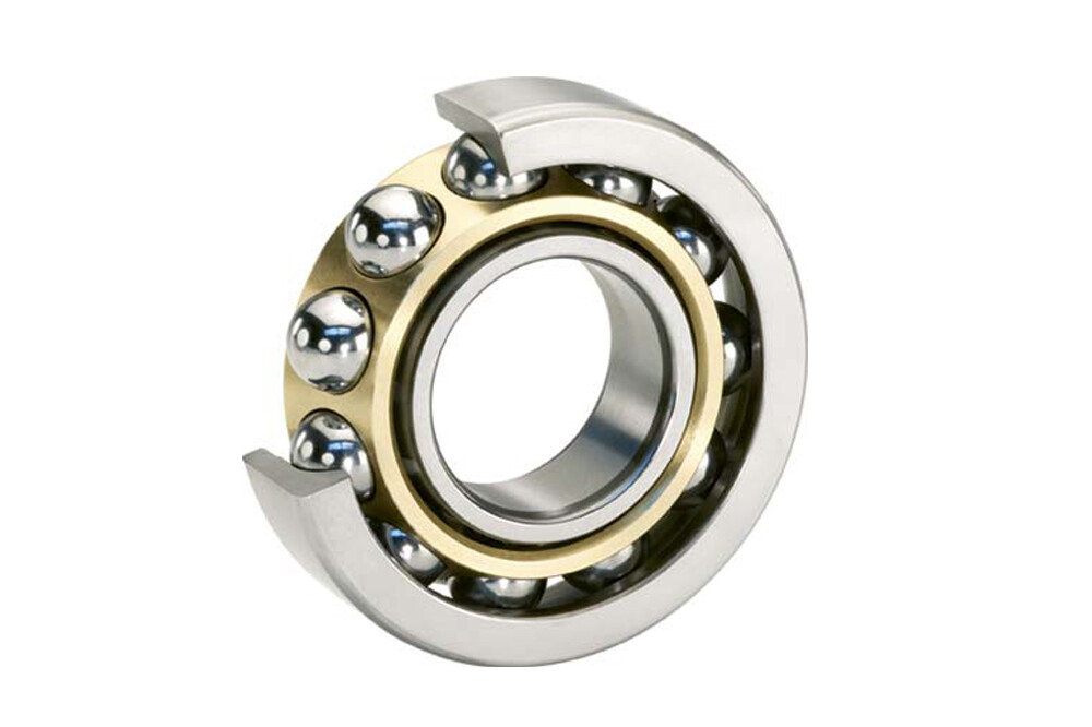
Figure 2: Single row angular contact ball bearing
The single-row bearing must be preloaded in the direction of the contact angle as it can only handle axial loads in that direction. Two single-row bearings can be fitted in back to back, face to face, or tandem arrangements:
Back-to-back: Back-to-back mounted angular ball bearings can accommodate both radial and axial loads in any direction. The distance between the bearing center and loading point (D) is larger than other mounting methods, it can therefore handle large momentary and alternating radial load forces. This mounting method is the most common (Figure 3-A).
Face-to-face: Through this mounting sequence the bearing can handle radial and axial loads in either direction. However, because the distance between the bearing center and loading point (D) is smaller through this mount, momentary and alternating radial force capacity is lower (Figure 3-B).
Tandem: A tandem mount can accommodate single direction axial loads as well as radial loads. Because the loads on the axis are received by both bearings it can handle heavy axial loads (Figure 3-C).

Figure 3: Single row angular contact bearing mounting methods: back-to-back (A), face-to-face (B), and tandem (C). The distance between the bearing center and loading point (D).
| Part Number | Seal Type | Bore Dia | Outer Dia | Width | Ring Material | Dynamic Radial Load | Static Radial Load |
| 305256 D | Open | 120 mm | 190 mm | 66 mm | 52100 Chrome Steel | 182 kN | 232 kN |
| 305262 D | Open | 180 mm | 259.5 mm | 66 mm | 52100 Chrome Steel | 225 kN | 310 kN |
| 305263 D | Open | 200 mm | 289.5 mm | 76 mm | 52100 Chrome Steel | 302 kN | 475 kN |
| 305263 DA | Open | 200 mm | 289.5 mm | 76 mm | 52100 Chrome Steel | 302 kN | 475 kN |
| 305264 D | Open | 230 mm | 329.5 mm | 80 mm | 52100 Chrome Steel | 351 kN | 600 kN |
| 305269 D | Open | 280 mm | 389.5 mm | 92 mm | 52100 Chrome Steel | 403 kN | 750 kN |
| 305270 D | Open | 260 mm | 369.5 mm | 92 mm | 52100 Chrome Steel | 397 kN | 710 kN |
| 305272 D | Open | 220 mm | 309.5 mm | 76 mm | 52100 Chrome Steel | 312 kN | 520 kN |
| 305272 DA | Open | 220 mm | 309.5 mm | 76 mm | 52100 Chrome Steel | 312 kN | 520 kN |
| 305272 DB | Open | 220 mm | 309.5 mm | 76 mm | 52100 Chrome Steel | 312 kN | 520 kN |
| 305283 D | Open | 150 mm | 230 mm | 70 mm | 52100 Chrome Steel | 203 kN | 285 kN |
| 305283 DA | Open | 150 mm | 230 mm | 70 mm | 52100 Chrome Steel | 203 kN | 285 kN |
| 305286 D | Open | 150 mm | 225 mm | 73 mm | 52100 Chrome Steel | 182 kN | 265 kN |
| 305288 DA | Open | 180 mm | 250 mm | 70 mm | 52100 Chrome Steel | 190 kN | 285 kN |
| 305338 D | Open | 190 mm | 269.5 mm | 66 mm | 52100 Chrome Steel | 270 kN | 415 kN |
| 305428 D | Open | 200 mm | 279.5 mm | 76 mm | 52100 Chrome Steel | 242 kN | 380 kN |
| 305608 | Open | 160 mm | 215 mm | 56 mm | 52100 Chrome Steel | 135 kN | 220 kN |
| 305608 B | Open | 160 mm | 215 mm | 56 mm | 52100 Chrome Steel | 135 kN | 220 kN |
| 3200 A-2RS1TN9/MT33 | Sealed | 10 mm | 30 mm | 14 mm | 52100 Chrome Steel | 7.61 kN | 4.3 kN |
| 3200 A-2ZTN9/MT33 | Shielded | 10 mm | 30 mm | 14 mm | 52100 Chrome Steel | 7.61 kN | 4.3 kN |
| 3200 ATN9 | Open | 10 mm | 30 mm | 14 mm | 52100 Chrome Steel | 7.61 kN | 4.3 kN |
| 3201 A-2RS1TN9/MT33 | Sealed | 12 mm | 32 mm | 15.9 mm | 52100 Chrome Steel | 10.1 kN | 5.6 kN |
| 3201 A-2ZTN9/MT33 | Shielded | 12 mm | 32 mm | 15.9 mm | 52100 Chrome Steel | 10.1 kN | 5.6 kN |
| 3201 ATN9 | Open | 12 mm | 32 mm | 15.9 mm | 52100 Chrome Steel | 10.1 kN | 5.6 kN |
| 3202 A-2RS1TN9/MT33 | Sealed | 15 mm | 35 mm | 15.9 mm | 52100 Chrome Steel | 11.2 kN | 6.8 kN |
| 3202 A-2ZTN9/MT33 | Shielded | 15 mm | 35 mm | 15.9 mm | 52100 Chrome Steel | 11.2 kN | 6.8 kN |
| 3202 ATN9 | Open | 15 mm | 35 mm | 15.9 mm | 52100 Chrome Steel | 11.2 kN | 6.8 kN |
| 3203 A-2RS1TN9/MT33 | Sealed | 17 mm | 40 mm | 17.5 mm | 52100 Chrome Steel | 14.3 kN | 8.8 kN |
| 3203 A-2ZTN9/MT33 | Shielded | 17 mm | 40 mm | 17.5 mm | 52100 Chrome Steel | 14.3 kN | 8.8 kN |
| 3203 ATN9 | Open | 17 mm | 40 mm | 17.5 mm | 52100 Chrome Steel | 14.3 kN | 8.8 kN |
| 3204 A | Open | 20 mm | 47 mm | 20.6 mm | 52100 Chrome Steel | 20.4 kN | 12.9 kN |
| 3204 A-2RS1 | Sealed | 20 mm | 47 mm | 20.6 mm | 52100 Chrome Steel | 20.4 kN | 12.9 kN |
| 3204 A-2RS1TN9/MT33 | Sealed | 20 mm | 47 mm | 20.6 mm | 52100 Chrome Steel | 20.4 kN | 12.9 kN |
| 3204 A-2Z | Shielded | 20 mm | 47 mm | 20.6 mm | 52100 Chrome Steel | 20.4 kN | 12.9 kN |
| 3204 A-2ZTN9/MT33 | Shielded | 20 mm | 47 mm | 20.6 mm | 52100 Chrome Steel | 20.4 kN | 12.9 kN |
| 3204 ATN9 | Open | 20 mm | 47 mm | 20.6 mm | 52100 Chrome Steel | 20.4 kN | 12.9 kN |
| 3205 A | Open | 25 mm | 52 mm | 20.6 mm | 52100 Chrome Steel | 22 kN | 15.3 kN |
| 3205 A-2RS1 | Sealed | 25 mm | 52 mm | 20.6 mm | 52100 Chrome Steel | 22 kN | 15.3 kN |
| 3205 A-2RS1TN9/MT33 | Sealed | 25 mm | 52 mm | 20.6 mm | 52100 Chrome Steel | 22 kN | 15.3 kN |
| 3205 A-2Z | Shielded | 25 mm | 52 mm | 20.6 mm | 52100 Chrome Steel | 22 kN | 15.3 kN |
| 3205 A-2ZTN9/MT33 | Shielded | 25 mm | 52 mm | 20.6 mm | 52100 Chrome Steel | 22 kN | 15.3 kN |
| 3206 A | Open | 30 mm | 62 mm | 23.8 mm | 52100 Chrome Steel | 30.5 kN | 22 kN |
| 3206 A-2RS1 | Sealed | 30 mm | 62 mm | 23.8 mm | 52100 Chrome Steel | 30.5 kN | 22 kN |
| 3206 A-2RS1TN9/MT33 | Sealed | 30 mm | 62 mm | 23.8 mm | 52100 Chrome Steel | 30.5 kN | 22 kN |
| 3206 A-2Z | Shielded | 30 mm | 62 mm | 23.8 mm | 52100 Chrome Steel | 30.5 kN | 22 kN |
| 3206 A-2ZTN9/MT33 | Shielded | 30 mm | 62 mm | 23.8 mm | 52100 Chrome Steel | 30.5 kN | 22 kN |
| 3206 ATN9 | Open | 30 mm | 62 mm | 23.8 mm | 52100 Chrome Steel | 30.5 kN | 22 kN |
| 3207 A | Open | 35 mm | 72 mm | 27 mm | 52100 Chrome Steel | 40.5 kN | 30 kN |
| 3207 A-2RS1 | Sealed | 35 mm | 72 mm | 27 mm | 52100 Chrome Steel | 40.5 kN | 30 kN |
| 3207 A-2RS1TN9/MT33 | Sealed | 35 mm | 72 mm | 27 mm | 52100 Chrome Steel | 40.5 kN | 30 kN |
| 3207 A-2Z | Shielded | 35 mm | 72 mm | 27 mm | 52100 Chrome Steel | 40.5 kN | 30 kN |
| 3207 A-2ZTN9/MT33 | Shielded | 35 mm | 72 mm | 27 mm | 52100 Chrome Steel | 40.5 kN | 30 kN |
| 3207 ATN9 | Open | 35 mm | 72 mm | 27 mm | 52100 Chrome Steel | 40.5 kN | 30 kN |
| 3208 A | Open | 40 mm | 80 mm | 30.2 mm | 52100 Chrome Steel | 48 kN | 36.5 kN |
| 3208 A-2RS1 | Sealed | 40 mm | 80 mm | 30.2 mm | 52100 Chrome Steel | 48 kN | 36.5 kN |
| 3208 A-2RS1TN9/MT33 | Sealed | 40 mm | 80 mm | 30.2 mm | 52100 Chrome Steel | 48 kN | 36.5 kN |
| 3208 A-2Z | Shielded | 40 mm | 80 mm | 30.2 mm | 52100 Chrome Steel | 48 kN | 36.5 kN |
| 3208 A-2ZTN9/MT33 | Shielded | 40 mm | 80 mm | 30.2 mm | 52100 Chrome Steel | 48 kN | 36.5 kN |
| 3208 ATN9 | Open | 40 mm | 80 mm | 30.2 mm | 52100 Chrome Steel | 48 kN | 36.5 kN |
| 3209 A | Open | 45 mm | 85 mm | 30.2 mm | 52100 Chrome Steel | 52 kN | 41.5 kN |
| 3209 A-2RS1 | Sealed | 45 mm | 85 mm | 30.2 mm | 52100 Chrome Steel | 52 kN | 41.5 kN |
| 3209 A-2RS1TN9/MT33 | Sealed | 45 mm | 85 mm | 30.2 mm | 52100 Chrome Steel | 52 kN | 41.5 kN |
| 3209 A-2Z | Shielded | 45 mm | 85 mm | 30.2 mm | 52100 Chrome Steel | 52 kN | 41.5 kN |
| 3209 A-2ZTN9/MT33 | Shielded | 45 mm | 85 mm | 30.2 mm | 52100 Chrome Steel | 52 kN | 41.5 kN |
| 3209 ATN9 | Open | 45 mm | 85 mm | 30.2 mm | 52100 Chrome Steel | 52 kN | 41.5 kN |
| 3210 A | Open | 50 mm | 90 mm | 30.2 mm | 52100 Chrome Steel | 51 kN | 42.5 kN |
| 3210 A-2RS1 | Sealed | 50 mm | 90 mm | 30.2 mm | 52100 Chrome Steel | 51 kN | 42.5 kN |
| 3210 A-2RS1TN9/MT33 | Sealed | 50 mm | 90 mm | 30.2 mm | 52100 Chrome Steel | 51 kN | 42.5 kN |
| 3210 A-2Z | Shielded | 50 mm | 90 mm | 30.2 mm | 52100 Chrome Steel | 51 kN | 42.5 kN |
| 3210 A-2ZTN9/MT33 | Shielded | 50 mm | 90 mm | 30.2 mm | 52100 Chrome Steel | 51 kN | 42.5 kN |
| 3210 ATN9 | Open | 50 mm | 90 mm | 30.2 mm | 52100 Chrome Steel | 51 kN | 42.5 kN |
| 3211 A | Open | 55 mm | 100 mm | 33.3 mm | 52100 Chrome Steel | 61 kN | 52 kN |
| 3211 A-2RS1 | Sealed | 55 mm | 100 mm | 33.3 mm | 52100 Chrome Steel | 61 kN | 52 kN |
| 3211 A-2Z | Shielded | 55 mm | 100 mm | 33.3 mm | 52100 Chrome Steel | 61 kN | 52 kN |
| 3211 ATN9 | Open | 55 mm | 100 mm | 33.3 mm | 52100 Chrome Steel | 61 kN | 52 kN |
| 3212 A | Open | 60 mm | 110 mm | 36.5 mm | 52100 Chrome Steel | 75 kN | 64 kN |
| 3212 A-2RS1 | Sealed | 60 mm | 110 mm | 36.5 mm | 52100 Chrome Steel | 75 kN | 64 kN |
| 3212 A-2RS1TN9/MT33 | Sealed | 60 mm | 110 mm | 36.5 mm | 52100 Chrome Steel | 75 kN | 64 kN |
| 3212 A-2Z | Shielded | 60 mm | 110 mm | 36.5 mm | 52100 Chrome Steel | 75 kN | 64 kN |
| 3212 ATN9 | Open | 60 mm | 110 mm | 36.5 mm | 52100 Chrome Steel | 75 kN | 64 kN |
| 3213 A | Open | 65 mm | 120 mm | 38.1 mm | 52100 Chrome Steel | 80.6 kN | 73.5 kN |
| 3213 A-2RS1 | Sealed | 65 mm | 120 mm | 38.1 mm | 52100 Chrome Steel | 80.6 kN | 73.5 kN |
| 3213 A-2Z | Shielded | 65 mm | 120 mm | 38.1 mm | 52100 Chrome Steel | 80.6 kN | 73.5 kN |
| 3214 A | Open | 70 mm | 125 mm | 39.7 mm | 52100 Chrome Steel | 88.4 kN | 80 kN |
| 3214 A-2Z | Shielded | 70 mm | 125 mm | 39.7 mm | 52100 Chrome Steel | 88.4 kN | 80 kN |
| 3215 A | Open | 75 mm | 130 mm | 41.3 mm | 52100 Chrome Steel | 95.6 kN | 88 kN |
| 3215 A-2Z | Shielded | 75 mm | 130 mm | 41.3 mm | 52100 Chrome Steel | 95.6 kN | 88 kN |
| 3216 A | Open | 80 mm | 140 mm | 44.4 mm | 52100 Chrome Steel | 106 kN | 95 kN |
| 3217 A | Open | 85 mm | 150 mm | 49.2 mm | 52100 Chrome Steel | 124 kN | 110 kN |
| 3218 A | Open | 90 mm | 160 mm | 52.4 mm | 52100 Chrome Steel | 130 kN | 120 kN |
| 3219 A | Open | 95 mm | 170 mm | 55.6 mm | 52100 Chrome Steel | 159 kN | 146 kN |
| 3220 A | Open | 100 mm | 180 mm | 60.3 mm | 52100 Chrome Steel | 178 kN | 166 kN |
| 3222 A | Open | 110 mm | 200 mm | 69.8 mm | 52100 Chrome Steel | 212 kN | 212 kN |
| 3302 A-2RS1 | Sealed | 15 mm | 42 mm | 19 mm | 52100 Chrome Steel | 15.1 kN | 9.3 kN |
| 3302 A-2RS1TN9/MT33 | Sealed | 15 mm | 42 mm | 19 mm | 52100 Chrome Steel | 15.1 kN | 9.3 kN |
| 3302 A-2Z | Shielded | 15 mm | 42 mm | 19 mm | 52100 Chrome Steel | 15.1 kN | 9.3 kN |
| 3302 A-2ZTN9/MT33 | Shielded | 15 mm | 42 mm | 19 mm | 52100 Chrome Steel | 15.1 kN | 9.3 kN |
| 3302 ATN9 | Open | 15 mm | 42 mm | 19 mm | 52100 Chrome Steel | 15.1 kN | 9.3 kN |
| 3303 A-2RS1 | Sealed | 17 mm | 47 mm | 22.2 mm | 52100 Chrome Steel | 21.6 kN | 12.7 kN |
| 3303 A-2RS1TN9/MT33 | Sealed | 17 mm | 47 mm | 22.2 mm | 52100 Chrome Steel | 21.6 kN | 12.7 kN |
The double row angular contact ball bearing is similar to two single-row bearings arranged back-to-back. In addition to radial and axial loads, they are also capable of absorbing tilting moments. The advantages of double-row contact bearings include:
While typically expensive than single-row bearings, double-row bearings can be economical in the long run.
Take up less axial space which is useful when two single-row bearings would take up too much space
Accommodates radial and axial loads, as well as tilting moments

Figure 4: Double row angular contact ball bearing
The 4-point contact ball bearing is similar to a single-row angular ball bearing It consists of an outer race that is flanked on both sides, an inner race is also flanked on both sides with a split in the middle, and steel balls circled by a cage. The flanks, or flanges, are symmetrical unlike single and double angular contact bearings.
There are several advantages of four-point contact ball bearings:
The split inner raceways of four-point contact ball bearings allow for easy mounting and dismounting of the bearing for maintenance.
The recess in the inner raceway allows for better oil flow.
These bearings work in a similar fashion to double-row or two single-row mounted angular contact bearings but take up less space.
Allows for loads in both axial and radial directions.
High load-carrying capacity due to a relatively higher number of balls than other ball bearings.

Figure 5: Four point contact ball bearing
Selection Criteria
When selecting an angular contact bearing, the main considerations revolve around speed, load type, load magnitude, seal type, tolerances and bearing size:
Speed: The speed an angular ball bearing can operate on depends on various factors such as ball angle, lubrication type, bearing size. When choosing a bearing compare your operational speed needs, desired lubrication type, and required load capacity to determine the speed capacity of your bearing. Keeping in mind that the operational speed of grease lubrication is lower than oil lubrication, info on this can be found in our Tribology series of articles and our bearing lubrication article. A smaller ball angle will also be able to achieve higher speeds, yet sacrifice load-bearing capacity.
Loads: Angular ball bearings are capable of handling both radial and axial loads. The choice between single, double, or four-point angular ball bearings, depends on the type, direction, and amount of loads present in the application. The end-user should also include the static radial load capacity, the maximum static load a bearing can withstand without excessive deformation; and the dynamic radial load, a constant load a bearing can endure for a preset amount of revolutions, typically one million revolutions.
Lubrication and seal type: Choose between relubricate, typically an open or shielded seal design for oil and grease; pre-lubricated, typically a shielded or closed seal design for oil and grease; or solid lubrication, polymer-based solid lubrication typically in a closed design.
Dimensions: Choose bearing dimension based on the type of load, amount of load, size of shaft, or the sie of the housing.
AUB manufactures angular contact bearings
AUB is a professional angular contact bearing manufacturer in China. Today we are a globally successful company in the development and manufacture of rolling bearings and supply than 600 customers in over 35 countries. Whether standard or special bearings, whether for original equipment or replacement requirements – we offer you the best possible.
Accommodating axial and radial forces
Suitable for very high speeds
Assembled in pairs
Single row angular contact ball bearings have angular raceways for the inner and outer rings and the resulting force-transmitting contact angles. Therefore, an axial load will always cause a radial load and vice versa, which is why angular contact ball bearings are always used in combination with a second bearing. When paired, in addition to radial forces, they can also absorb axial forces and combined forces, especially for high speeds. Single row angular contact ball bearings cannot be disassembled.
Dimensions and Tolerances
AUB offers angular contact ball bearings in standard tolerances (PN) according to DIN 620-2 (Roller bearing tolerances) and ISO 492 (Radial bearings – Dimensional and geometrical tolerances). All other deviations or special tolerances must be specified on the order.
Standard
The general dimensions of single row angular contact ball bearings are standardised in DIN 628-1 (Angular contact radial ball bearings), DIN 616 (Rolling bearings – Dimensions), and ISO 15 (Radial bearings – Boundary dimensions, general plan).
Bearing Design
Angular contact ball bearings are self-latching radial bearings that cannot be disassembled. In addition to high radial forces, they can absorb single-sided axial forces as well as, in combination with a second mirror-image arranged angular contact ball bearing, two-sided axial forces. For combined bearing sets there is a distinction between O-, X- or tandem arrangement based on pressure line contact. Bearings in X-arrangement are less suitable for the absorption of moment loads while the O-arrangement is very rigid and only allows small overturning clearance. For tandem arrangements, the pressure lines of two bearings run in one direction which results in only single-sided absorption of axial forces. In the process, the axial load is absorbed by both bearings in the pair and the axial load capacity is increased.

Different positioning of angular contact ball bearings in X-, O-, and tandem arrangement

Single row angular contact ball bearing in its default design; α – contact angle
The axial load capacity of an angular contact ball bearing is increased with a larger contact angle. Angular contact ball bearings of the series 72B, 73B and 74B are by default supplied with a contact angle of 40°, the series 708, 709, 718, 719 and 70 (without suffix B) with 30°.
Bearing Clearance and Preload
Angular contact ball bearings are divided into clearance classes and preload classes. These are not standardised. AUB bearing clearance classes and preload classes are defined by suffixes.
Cage
By default, angular contact ball bearings by AUB are equipped with a roller riding solid brass window-type cage (suffix: MP). Other cage designs are available on request or chosen for specific applications and labelled accordingly on the bearing.

Special Suffixes
B Modified internal design, contact angle 40°
D Modified internal design, contact angle 20°
E Modified internal design, contact angle 25°
Compensation of Angular Misalignments
Single row angular contact ball bearings are of limited suitability for compensation of misalignments. The admissible misalignment between inner and outer ring depends on the bearing size, the internal bearing design, the clearance fit, and the acting of forces and moments. Misalignments cause harmful ball movement and produce additional stresses in the bearing which reduce its operating life.
Speed
AUB distinguishes between kinematic limiting speed nG and thermal reference speed nth. The kinematic limiting speed is a practical mechanical limit value and is based on the mechanical fatigue strength of the rolling bearing as a function of its installation situation and lubrication. The limit speed must not be exceeded even under optimum operating conditions without prior consultation with AUB.
The thermal reference speed represents the equilibrium between the heat generated in the bearing by friction and the heat flow dissipated. It is standardised in DIN ISO 15312 (Rolling bearings – Thermal reference speed).
Admissible Operating Temperatures
The admissible operating temperature of a bearing is limited by cage material, dimensional stability of the bearing components (ball race and rolling elements), as well as lubrication. By default, AUB bearings are stabilised up to 200°C (S1). KRW provides roller bearings for higher operating temperatures on request.
Dimensioning
For dynamically loaded bearings
The service life formula according to ISO 281 L10 = (C/P)p for dynamically loaded bearings requires an equivalent load (P) from constant direction and size. To calculate P, calculation factors and the ratio of axial and radial load are required. This is shown in the following equations.
Equivalent Dynamic Bearing Load P
a) Single bearings and tandem arrangement
The equivalent bearing load P for dynamically loaded single bearings or bearings in tandem arrangement depends on the ratio Fa/Fr (axial force / radial force). The equivalent dynamic bearing load can then be determined using the following formula:

| P | equivalent dynamic load | [kN] |
| Fr | dynamic radial force | [kN] |
| Fa | dynamic axial force | [kN] |
| e | calculation factor, see chart | [-] |
| X | calculation factor, see chart | [-] |
| Y | calculation factor, see chart | [-] |
| Series | e | X | Y |
| 708, 709, 718, 719 | 0,80 | 0,39 | 0,76 |
| 72B, 73B, 74B | 1,14 | 0,35 | 0,57 |
b) O- and X-arrangement
The equivalent bearing load P for dynamically loaded bearings in O- or X-arrangement depends on the ratio Fa/Fr (axial force / radial force). The equivalent dynamic bearing load can then be determined using the following formula:

| P | equivalent dynamic load | [kN] |
| Fr | dynamic radial force | [kN] |
| Fa | dynamic axial force | [kN] |
| X | calculation factor, see chart | [-] |
| Y | calculation factor, see chart | [-] |
| eries | Fa / Fr | X | Y |
| 708, 709, 718, 719 | ≤ 0,80 | 1 | 0,78 |
| > 0,80 | 0,63 | 1,24 | |
| 72B, 73B, 74B | ≤ 1,14 | 1 | 0,55 |
| > 1,14 | 0,57 | 0,93 |
Resulting axial force for O- and X-arranged roller bearings
Due to the angular raceways, when a radial force occurs, angular contact ball bearings generate an axial reactive force which is relevant to the bearing dimensioning. When a shaft is supported by two identical or differently sized angular contact ball bearings, the radial load of one bearing produces an axial load for the other bearing. This internal resulting force must be considered when determining the total axial load. The value of the total axial load on a single bearing is determined with the following formulas:
| case | load ratio | outer force | resulting axial force Fa | |
| bearing A | bearing B | |||
| 1 | FrA / YA ≤ FrB / YB | Ka ≥ 0 | Fa = Ka + 0,5 ∙ FrB / YB | Fa is not considered in the calculation |
| 2 | FrA / YA > FrB / YB | Ka > 0,5 · ( FrA / Ya – FrB / YB ) | Fa = Ka + 0,5 ∙ FrB / YB | Fa is not considered in the calculation |
| 3 | FrA / YA > FrB / YB | Ka ≤ 0,5 ∙ ( FrA /YA – FrB /YB ) | Fa is not considered in the calculation | Fa = 0,5 ∙ FrA / YA – Ka |
To the formulas applies that the bearings being affected by the outer axial force Ka are marked with A and the counter bearings with B. All bearings are backlash-free and considered without preload.
| FrA | radial force in bearing A | [kN] |
| FrB | radial force in bearing B | [kN] |
| YA | calculation factor for bearing A (see chart X- and O-arrangement) | [-] |
| YB | calculation factor for bearing B (see chart X- and O-arrangement) | [-] |
| Ka | outer axial force | [kN] |
| Fa | resulting axial force | [kN] |

c) Reduction of dynamic load rating in a bearing set
For identical angular contact ball bearings assembled directly side by side in X-, O-, or tandem arrangement, the load rating of the bearing set must be reduced. For the dynamic load rating, the following correlation applies:

| Cr | dynamic load rating of the bearing set | [kN] |
| Cr, single bearing | dynamic load rating of the single bearing | [kN] |
| i | number of identical bearings in bearing set | [-] |
For statically loaded bearings
Dynamic dimensioning loses its validity for bearings rotating at very low speeds (n x dm ≤ 4000 mm/min). The static load safety factor S0 is calculated as follows:

| S0 | static load safety factor | [-] |
| C0 | basic static load rating (from bearing chart) | [kN] |
| P0 | equivalent static bearing load | [kN] |
| n | bearing speed | [min-1] |
| dm | mean bearing diameter [dm = (D+d)/2] | [mm] |
Static load capacity
a) single bearings or tandem arrangement
For statically loaded single row or tandem arranged angular contact ball bearings, the following correlations apply:

| F0r | max. radial static force | [kN] |
| F0a | max. axial static force | [kN] |
| Series | X | Y |
| 708, 709, 718, 719 | 0,5 | 0,33 |
| 72B, 73B, 74B | 0,5 | 0,26 |
b) X- und O-arrangement
For statically loaded angular contact ball bearings in X- or O-arrangement, the following correlations apply:
| F0r | max. radial static force | [kN] |
| F0a | max. axial static force | [kN] |
| Series | X | Y |
| 708, 709, 718, 719 | 1 | 0,66 |
| 72B, 73B, 74B | 1 | 0,52 |
c) Reduction of static load rating in a bearing set
For identical angular contact ball bearings assembled directly side by side in X-, O-, or tandem arrangement, the load rating of the bearing set must be calculated. For the static load rating, the following correlation applies:

| C0 | static load rating of the bearing set | [kN] |
| C0, single bearing | static load rating of the single bearing | [kN] |
| i | number of identical bearings in bearing set | [-] |
Minimum Radial Load
A minimum load is required for the reliable operation of a rolling bearing. If the minimum load is not reached, slippage may occur. The minimum radial load for angular contact ball bearings is roughly assumed to be 1% of the static load rating C0 of the bearing. If the value falls below this value, consult KRW Application Engineering.
Typical applications of angular contact ball bearings
Due to their ability to accommodate heavy loads, angular contact ball bearings are ideal for heavy machinery and agricultural equipment. These bearings help run pumps, electric motors, gearboxes, steel mills, windmills, conveyor belts and other high speed applications.
FAQs
In which direction do angular contact bearings provide load capacity?
Single-row and tandem ball bearings provide one-directional thrust for axial loads. The contact angle guides the direction, which also determines the gradient of the combined load.
Do angular contact bearings need preload?
To remove excess play during bearing installation, users sustain a load pressure called preloading. Angular contact bearings require preload because they have to work in the pre-defined direction for axial loads.


