
Bearing Manufacturer & Supplier
Specialize in ball bearings, roller bearings, thrust bearings, thin section bearings etc.
Follow me on:
![]()
![]()
The Ultimate Guide to Bearing Installation and Removal
Bearing installation and removal is an important skill that requires the correct equipment, procedures and expertise. In order to ensure the stable operation of the bearing system and reach the expected service life, the bearings need to be installed correctly. If the installation is incorrect, the bearings will be damaged prematurely, which may affect the machine experience, increase noise and heat, or cause the machine to shut down and cause property damage. , causing health hazards to users. This blog aims to introduce some key points and techniques for bearing installation and removal.
Procedures before bearing installation
Before installing the bearing, there are procedures such as cleaning, drying, and (grease sealing) test operation. The operation should be carried out on the basis of observing various precautions. In addition, since the sealed bearings contain grease inside, they must not be cleaned and dried. Use a clean cotton cloth to wipe the external anti-rust oil clean before proceeding with installation.
Clean bearings
Before starting installation, make sure the bearing housing and shaft are clean and free of burrs. After soaking the bearings in highly volatile solvents such as refined kerosene and naphthesol and turning them by hand, use gasoline, ethanol, etc. to remove the refined kerosene, etc. When blowing off the cleaning oil with an air gun, pay attention to the cleanliness of the air. Bearings that use oil lubrication can be installed and operated directly, but it is recommended to apply lubricating oil or low-viscosity oil after installation before working.

Dry the bearings
When using grease lubrication, in order to prevent grease from flowing out, the bearing needs to be fully dry. In addition, grease should be sealed immediately after drying. Drying can be done with warm air (pay attention to the cleanliness of the air) or in a constant temperature bath.
Encapsulated grease.
After sealing the grease, turn the rolling part by hand to fully coat the grease. Ball bearings can use a syringe to pack equal amounts of grease between the balls. When there is a raceway ring guide cage, it is recommended to use a small tool such as a spatula to apply it on the guide surface of the cage. When the inner ring rolling surface cannot be sealed due to the narrow space of the inner ring, the outer ring rolling surface is sealed. At this time, try your best to rotate by hand to allow the grease to penetrate into the inner ring. When applying grease to the outer diameter surface (inner diameter surface) of a roller bearing, turn the roller with your fingertips to allow the grease to penetrate into the inner ring (outer ring).

Test run the bearings
1. Oil gas and oil mist lubrication. In oil lubrication, the bearing temperature reaches a stable state in a short period of time before reaching the peak value, so the test run is relatively simple. It is recommended to maintain the speed at 2000-3000 rpm for about 30 minutes and gradually increase it to the working speed. However, when dmn (rolling element center diameter * rotation speed) exceeds the range of 1 million times, in order to ensure safety, the speed should be increased in units of 1000-2000 revolutions per minute.
2. Grease lubrication. In grease lubrication, a trial run is very important to stabilize the temperature rise. During trial operation, after the rotation speed increases, the temperature rises quickly. After reaching the peak value, the temperature will slowly stabilize. It takes some time to reach stability.
3. Ball bearings. It is recommended to use 1000-2000 rpm as the unit, and then increase the speed after the temperature stabilizes. When dmn (rolling element center diameter * rotational speed) exceeds the range of 400,000 times, for safety reasons, the speed should be increased by 500-1000 revolutions per minute.
4. Roller bearings. Compared with ball bearings, roller bearings have a longer peak temperature during commissioning and a longer time to reach a stable temperature. In addition, since the temperature may rise due to the reentry of grease and the temperature change may not be stable, the engine should be operated at the maximum speed for a long time. It is recommended to use 500-1000 rpm as the unit, and then increase the speed after the temperature reaches a stable level. When dmn (rolling element center diameter * rotational speed) exceeds the range of 300,000 times, for safety reasons, the speed should be increased in units of 300 rpm.
Bearing installation
Bearing installation will affect accuracy, life and performance. Therefore, please fully study the installation of bearings, that is, please operate according to the operating standards including the following items. For bearings that have been lubricated with grease and have oil seals or dust covers on both sides, the seal ring bearing does not need to be cleaned before installation. Bearing installation should be based on the bearing structure, size and matching properties of the bearing components. Bearing installation generally uses the following methods:
Press-fit Bearing installation
When the inner ring of the bearing has a tight fit with the shaft, and the outer ring has a loose fit with the bearing seat hole, a press can be used to press the bearing onto the shaft first, and then the shaft and the bearing are installed into the bearing seat hole. On the end face of the bearing inner ring, place an assembly sleeve (copper or mild steel) made of soft metal material. The inner diameter of the assembly sleeve should be slightly larger than the diameter of the journal, and the outer diameter should be slightly smaller than the rib of the inner ring of the bearing. Pressed on the cage. When the outer ring of the bearing and the bearing seat hole are tightly matched, and the inner ring and the shaft are loosely matched, the bearing can be pressed into the bearing seat hole first. At this time, the outer diameter of the assembly sleeve should be slightly smaller than the diameter of the seat hole. If the bearing ring is a tight fit with the shaft and seat hole, the installation inner ring and outer ring must be pressed into the shaft and seat hole at the same time. The structure of the assembly casing should be able to simultaneously press the end faces of the bearing inner ring and outer ring.

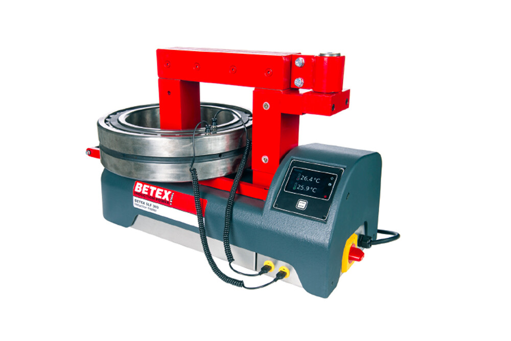
Heating installation
An installation method that uses a controlled heat source such as a heat gun or induction heater to heat the bearing or housing, using the principle of thermal expansion to convert a tight fit into a loose fit. It is a common and labor-saving installation method. Before hot installation, put the bearing or separable bearing ring into the oil tank and heat it evenly to 80-100°C, then take it out of the oil and install it on the shaft as soon as possible. In order to prevent the inner ring end face and the shaft shoulder from not fitting tightly after cooling, After the bearing has cooled down, it can be tightened axially. When the bearing outer ring is tightly matched with the light metal bearing seat, the hot fitting method of heating the bearing seat can avoid scratches on the mating surface. When using an oil tank to heat a bearing, there should be a grid at a certain distance from the bottom of the tank, or a hook is used to hang the bearing. The bearing cannot be placed on the bottom of the tank to prevent impurities from entering the bearing or uneven heating. There must be a thermometer in the oil tank. Strictly control the oil temperature not to exceed 100°C to prevent tempering effects and reduce the hardness of the ferrule.
Bearing induction heating is a simple solution for mounting bearings onto shafts. Induction heating is a non-contact, safe method for precisely heating conductive materials such as bearings, bushings and gears. The heating process changes the physical properties of the bearing metal, making the material or workpiece harder, softer, or bonded to the metal. Induction heaters produce an oscillating current that heats up bearings or metal when placed in the device’s magnetic field. Eddy currents cause the bearings to heat up and expand. Once the induction bearing heater reaches the target temperature, it is time to remove the heated bearing using safety gloves and place it on the shaft. As the bearing cools down, the bearing shrinks to fit the shaft. In general, bearing induction heaters are safe, clean and simple to replace bearings on a shaft safely, reliably and quickly.

Installation of tapered bore bearings
Bearings with tapered bores can be directly installed on the tapered journal, or on the tapered surface of the adapter sleeve and withdrawal sleeve. The tightness of the fit can be measured by the reduction in the bearing’s radial clearance. Therefore, it should be installed before installation. Measure the radial clearance of the bearing. During the installation process, the clearance should be measured frequently to achieve the required clearance reduction. During installation, locking nuts are generally used for installation, and heating installation methods can also be used.
Installation of thrust bearings
The overall fit of the thrust bearing and the shaft is generally a transition fit, and the fit between the seat ring and the bearing seat hole is generally a clearance fit. Therefore, this kind of bearing is easier to install. The central axis of the two-way thrust bearing should be fixed on the shaft to prevent relative movement. Rotate on the axis. Generally speaking, the installation method of bearings is that the shaft rotates, so the fit between the inner ring and the shaft is an over-win fit, and the fit between the bearing outer ring and the bearing chamber is a clearance fit.
Bearing removal
When replacing bearings, the first step is to remove the failed bearing, your best option is to use a puller and press. Using a puller to safely pull the bearing out of the outer race minimizes damage to the shaft and housing and saves time. In addition to the puller, a separator can also be used to disassemble the bearing. The separator is designed with two plates placed behind the bearing. The bearing is pulled out by the force on the plate. If a heavy bearing needs to be disassembled, the separator can use hydraulic pressure. Auxiliary cylinder supplies power. It is not recommended to use the removed bearing again, but it is necessary to carefully inspect the removed bearing to determine the cause of bearing failure and summarize experience to protect the bearing when using it in the future. Some bearing damage is invisible to the naked eye and may require advanced analysis tools to determine the cause of the failure. The removed bearings can be resent to the manufacturer, who will clean, inspect, measure, and re-grind the bearings. If they meet the conditions for reuse after inspection, they can be reused. This can save a lot of money when dealing with some large and expensive bearings.
Interference of the inner ring of the bearing and clearance fit of the outer ring
When the support dimensions are designed correctly, bearings with clearance fits can be removed with the orientation aligned as long as they are not deformed or rusted due to overuse and stuck on the matching parts. Reasonable disassembly of bearings under interference fit conditions is the core of bearing disassembly technology. Bearing interference fit is divided into inner ring interference and outer ring interference. The following will introduce these two situations separately.
Cylindrical shaft
Proper bearing disassembly requires the use of tools. For small size bearings, the conventional tool is a puller. Pullers are divided into two types: two-claw and three-claw, and are divided into threaded and hydraulic. The thread puller is a relatively traditional tool. Its operation is to align the center screw with the center hole of the shaft, apply a small amount of grease to the center hole of the shaft, hook the hook on the end face of the bearing inner ring, and use a wrench to twist the center rod. The bearing can be pulled out. The hydraulic puller uses a hydraulic device instead of the thread. When pressurized, the piston in the middle continues to extend, and the bearing will be continuously pulled out. It is faster than the traditional thread puller and the hydraulic device can quickly retreat. In some designs, the distance between the end face of the inner ring of the bearing and other components is small, and there is no operating space for the claws of a traditional puller. In this case, a two-piece splint can be used (as shown below), select a splint of appropriate size, and disassemble it separately. pressure. Parts of the plywood can be made thinner to penetrate into narrow spaces.


When the size of the bearing increases, the force required to disassemble the bearing also increases, and the general puller cannot be used, and special tooling needs to be designed for disassembly. The minimum force required for disassembly can be estimated based on the installation force required for the bearing to overcome the interference fit. The calculation formula is as follows:
F=0.5 *π *u*W*δ* E*(1-(d/d0)2)
F = Force (N)
μ = friction coefficient between the inner ring and the shaft, generally around 0.2
W = inner ring width (m)
δ = interference fit (m)
E = Young’s modulus 2.07×10¹¹ (Pa)
d = bearing inner diameter (mm)
d0=middle diameter of outer raceway of inner ring (mm)
π= 3.14
When the disassembly force is so great that it cannot be dismantled by ordinary methods, and the disassembly force generated by conventional methods is likely to damage the bearing, an oil hole is generally designed at the end of the shaft. The oil hole extends to the bearing position and then radially penetrates the shaft surface. An annular groove is added, and a hydraulic pump is used to pressurize the shaft end to expand the inner ring during disassembly, reducing the disassembly force.
When the size of the bearing is too large and simple hard pulling cannot be disassembled, the heating disassembly method needs to be used. Complete tools need to be prepared before operation, such as jacks, height gauges, spreaders, etc. The method of heating and disassembly is to directly wind the coil onto the raceway of the inner ring to heat it and expand it, so that the bearing can be easily disassembled. The same heating method is also applicable to cylindrical bearings with separable rollers. This method allows the bearing to be disassembled without damage.
Tapered shaft
Since the areas of the two end faces of the inner ring of a tapered bearing are significantly different, the large end face of the inner ring of the bearing is usually heated for disassembly. Use a flexible coil medium frequency induction heater to quickly heat the inner ring of the bearing to create a sufficient temperature difference with the shaft, thereby disassembling the inner ring of the bearing. Since tapered bearings are used in pairs, after one inner ring is removed, the other inner ring will inevitably be exposed to heat. If the inner ring of the bearing is placed in a position where the large end surface cannot be heated, the cage needs to be destroyed, the rollers removed, the inner ring body exposed, and the coil directly placed on the raceway for heating.
The heating temperature of the heater must be set not to exceed 120 degrees Celsius, because bearing disassembly requires a rapid temperature difference and operation process, not temperature. If the ambient temperature is very high or the interference is very large and the temperature difference is insufficient, dry ice (solid carbon dioxide) can be used as an auxiliary means. The dry ice can be placed on the inner wall of the hollow shaft to quickly reduce the temperature of the shaft (usually for such large-sized workpieces) , thereby increasing the temperature difference. For the disassembly of tapered bore bearings, do not completely remove the clamping nut or mechanism at the end of the shaft before disassembly. Only loosen it to avoid bearing falling accidents.

The disassembly of large-sized tapered shafts requires the use of disassembly oil holes. Taking the rolling mill’s four-row tapered bearing TQIT with a tapered bore as an example, the inner ring of the bearing is divided into three parts, two single-row inner rings and a double inner ring in the middle. There are three oil holes at the end of the roll, corresponding to the marks 1, 2,3, where 1 corresponds to the outermost inner ring, 2 corresponds to the double inner ring in the middle, and 3 corresponds to the innermost inner ring with the largest diameter. When disassembling, disassemble in sequence of serial numbers, and pressurize holes 1, 2, and 3 respectively. After all is completed, when the bearing can be lifted while driving, remove the hinge ring at the end of the shaft and the bearing is disassembled.
Removing the bearings on the cylindrical shaft diameter
When disassembling smaller bearings, the bearing ring can be removed from the shaft by gently tapping the side of the bearing ring with a suitable punch or, better still, using a mechanical puller (Figure 1). The grip should be applied to the inner ring or adjacent components. The disassembly process can be simplified if the shaft shoulder and the housing bore shoulder are provided with grooves to accommodate the puller’s grip. In addition, some threaded holes are machined at the hole shoulders to facilitate the bolts to push the bearings out (Figure 2). Large and medium-sized bearings often require force than machine tools can provide. Therefore, it is recommended to use hydraulic power tools or oil injection methods, or both together. This means that the shaft needs to be designed with oil holes and oil grooves (Figure 3).
Cold Disassembly

Figure 1

Figure 2

Figure 3
Hot disassembly
When disassembling the inner ring of needle roller bearings or NU, NJ, and NUP cylindrical roller bearings, the thermal disassembly method is suitable. Two commonly used heating tools: heating rings and adjustable induction heaters. Heated rings are typically used to install and disassemble the inner rings of small and medium-sized bearings of the same size. The heating ring is made of light alloy. The heating ring is radially slotted and equipped with an electrically insulated handle (Fig. 4). If inner rings of different diameters are frequently disassembled, it is recommended to use an adjustable induction heater. These heaters (Figure 5) quickly heat the inner ring without heating the shaft. When disassembling the inner rings of large cylindrical roller bearings, some special fixed induction heaters can be used.

Figure 4

Figure 5

Figure 6
Removing bearings mounted on conical shaft diameters
Small bearings can be removed by using a mechanical or hydraulically powered puller to pull the inner ring. Some pullers are equipped with spring-operated arms. Using this self-centering design of the puller can simplify the procedure and avoid damage to the journal. If the puller claw cannot be used on the inner ring, the bearing should be removed through the outer ring, or by using a puller combined with a puller blade (Figure 6). When using the oil injection method, the disassembly of medium and large bearings will be safer and simpler. This method injects hydraulic oil between two conical mating surfaces through oil holes and oil grooves under high pressure. Friction between the two surfaces is greatly reduced and creates an axial force that separates the bearing and shaft diameter.
Remove the bearing from the adapter sleeve
For small bearings installed on straight shafts with adapter sleeves, you can use a hammer to knock the small steel block evenly on the end face of the inner ring of the bearing to disassemble it (Figure 7). Before this, the adapter sleeve locking nut needs to be loosened several turns. For small bearings installed on adapter sleeves with stepped shafts, they can be disassembled by using a hammer to tap the small end face of the adapter sleeve lock nut through a special sleeve (Figure 8). Before this, the adapter sleeve locking nut needs to be loosened several turns. For bearings mounted on adapter sleeves with stepped shafts, the use of hydraulic nuts can make bearing removal easier. For this purpose, a suitable stop device must be installed close to the hydraulic nut piston (Figure 9). The oil filling method is a simpler method, but an adapter sleeve with oil holes and oil grooves must be used.

Figure 7

Figure 8

Figure 9
Disassemble the bearing on the withdrawal sleeve
When disassembling the bearing on the withdrawal sleeve, the locking device (such as locking nut, end plate, etc.) must be removed. For small and medium-sized bearings, lock nuts, hook wrenches or impact wrenches can be used to disassemble them (Figure 10). For medium and large bearings installed on the withdrawal sleeve, they can be easily removed using hydraulic nuts. It is recommended to install a stop device behind the hydraulic nut at the shaft end (Fig. 11). This stop device prevents the withdrawal sleeve and hydraulic nut from flying out of the shaft when the withdrawal sleeve is suddenly separated from the mating position.


Interference fit of bearing outer ring
The prerequisite for dismantling the bearing when the outer ring of the bearing has an interference fit is that the outer ring shoulder diameter cannot be less than the support diameter required by the bearing. The outer ring can be disassembled using the drawing tool diagram shown in the figure below. If the outer ring shoulder diameter of some applications requires complete coverage, the following two design options should be considered during the design stage:
• Two or three notches can be reserved at the step of the bearing seat so that the puller claws have a strong point for easy disassembly.
• Design four through-threaded holes on the back of the bearing seat to reach the end face of the bearing. They can be sealed with screw plugs at ordinary times. When disassembling, replace them with long screws. Tighten the long screws to gradually push out the outer ring.

When the bearing is large or the interference is large, the flexible coil induction heating method can also be used. Disassembly is carried out through the outer diameter of the heating box. The outer surface of the box must be regular and smooth to prevent local overheating. The center line of the box should be perpendicular to the ground, and use a jack to assist if necessary.