
Bearing Manufacturer & Supplier
Specialize in ball bearings, roller bearings, thrust bearings, thin section bearings etc.
Follow me on:


Guidelines for Crossed Roller Bearing Loading
The rolling elements of crossed roller bearings generally use cylindrical rollers or tapered rollers arranged in a cross state on the raceway. The rollers are separated by cages or spacers. The cross-arranged roller structure allows a single bearing to withstand various loads such as axial load, radial load and overturning moment. Compared with traditional structural bearings, the rigidity is increased by 3-4 times, and is suitable for various industrial rotating parts. , rotary tables, robots, CNC machine tools and other fields. This blog aims to introduce the types, characteristics, loads, influencing factors, calculation methods, etc. of crossed roller bearings, and provide constructive suggestions for you to choose suitable bearings.
Characteristics of Crossed Roller Bearings
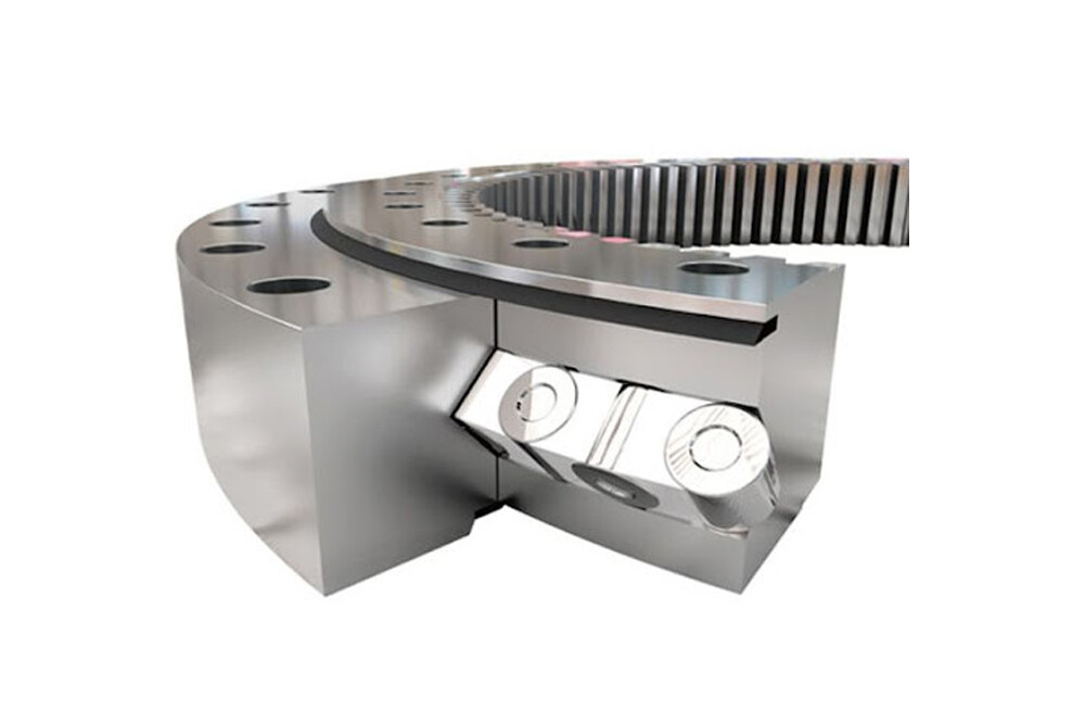
The internal structure of crossed roller bearings uses vertically crossed rollers arranged at 90°. Gaskets or spacers are installed between them to prevent the inclined rollers from rubbing against each other, effectively preventing the increase in rotational torque, and can withstand large radial loads. Axial loads and moment loads in all directions. In addition, there will be no one-sided contact or locking of the rollers; at the same time, because the inner and outer rings are split structures and the gap is adjustable, high-precision rotation can be obtained even if preload is applied. The size of the inner and outer rings of crossed roller bearings is minimized, especially the ultra-thin structure is close to the limit of small size and has high rigidity. Therefore, crossed roller bearings are most suitable for a wide range of applications such as joints or rotating parts of industrial robots, rotating tables of CNC machining centers, rotating parts of manipulators, precision rotating tables, medical instruments, measuring instruments, and IC manufacturing equipment.

Crossed roller bearings have excellent rotational accuracy and are usually used in precision instruments that require high rotational accuracy. They are easy to operate and install and save installation space. Crossed roller bearings are mainly divided into two types:
Crossed cylindrical roller bearings
Crossed cylindrical roller bearing is a kind of bearing in which cylindrical rollers are arranged vertically cross between the inner and outer rings of the bearing. The rollers and the raceways are in line contact with good rigidity. The elastic deformation of the bearing under load is very small, and it can simultaneously It can bear radial load, axial load and moment load, and is especially suitable for occasions requiring high rigidity and high rotation accuracy.

Crossed tapered roller bearings
Crossed tapered roller bearings have two rows of tapered rollers arranged vertically crosswise on a 90° V-shaped raceway surface through spacers. They can withstand loads in all directions, including radial loads and axial loads. Line contact on the raceway and roller construction provides great rotational accuracy, high stability and greater tilt stiffness.

Factors affecting the load of crossed roller bearings
Crossed roller bearings are specially designed to support rotational loads. Their special structure uses cross-arranged rollers to bear radial and axial loads. The load-carrying capacity of bearings is affected by many factors such as bearing materials, manufacturing processes, lubrication conditions and design structures.
1. Material: In terms of bearing materials, commonly used bearing materials include chromium steel, stainless steel, ceramics, etc. Chromium steel has high hardness and strength, but may be affected by high temperatures or corrosive environments; stainless steel performs better in corrosion resistance, but has relatively low strength; ceramic bearings are used for their high hardness, low friction, and corrosion resistance. Characteristics, used in some special occasions.
2. Manufacturing process: The manufacturing process has a direct impact on the quality and load-bearing capacity of the bearing. Precision machining technology can ensure the accuracy and stability of the bearing, thereby improving its load-bearing capacity. The accuracy of raceway shape and size is key to ensuring that the bearing can withstand the load.

3. Lubrication: Good lubrication is a key factor to ensure normal operation of bearings and improve load-bearing capacity. Appropriate grease and lubrication methods can reduce friction and wear, thereby extending the service life of bearings.
4. Design structure: A good design structure can improve the bearing’s distributed load capacity and lateral force resistance. The internal structural design of the bearing should fully consider the stress conditions to ensure the maximum load-bearing capacity.
5. Clearance: The accuracy and clearance of crossed roller bearings are the core of crossed roller bearings. The positive and negative clearance of the bearing will affect the stiffness, load, noise, life and speed of the cross rollers.
① When the working clearance is negative, the fatigue life of the bearing is long. As the negative clearance increases, the fatigue theoretical clearance decreases to a significant level. The rigidity of the bearing can be greatly improved and the noise of the bearing can be reduced.
②When the working clearance is positive, the rotation speed of the bearing will continue to increase. But at the same time, the bearings will also have shortcomings such as excessive noise and insufficient stiffness.
Calculating loads on crossed roller bearings
How do we calculate the load-carrying capacity of crossed roller bearings in actual work? Aubearing is a leading crossed roller bearing manufacturer in China. Based on many years of experience, it has summarized the formula for daily calculation of crossed roller bearings, as well as the requirements Some data collected. The load carrying capacity of crossed roller bearings can be calculated by the following formula:
Axial load: Cₐ = Kₐ * P
Radial load: Cᵣ = Kᵣ * P
In Where
Cₐ is the axial load capacity (N),
Cᵣ is the radial load capacity (N),
Kₐ is the axial load coefficient,
Kᵣ is the radial load coefficient,
P is the equivalent dynamic load (N).
The following data needs to be provided during the specific calculation process:
1. Axial load (Pₐ): refers to the axial force or axial moment acting on the shaft.
2. Radial load (Pᵣ): refers to the radial force or radial moment acting on the shaft.
3. Axial load coefficient (Kₐ): Determined by the direction of the axial load and stress distribution, the general value is 0.3-0.5.
4. Radial load coefficient (Kᵣ): Determined by the direction of radial load and stress distribution, the general value is 0.3-0.4.
The following points need to be noted during the calculation process:
1. Ensure the direction and type of load are correct, that is, distinguish between axial load and radial load.
2. Select the appropriate load factor according to the actual application situation to ensure the accuracy of the calculation results.
3. Pay attention to the unification of units and ensure that the units of all data are consistent.
4. For complex load conditions, they can be decomposed into axial and radial loads, calculated separately and then combined.